This value represents the height of the solid at the specified point. As a consequence:
- you can impose ITP Height wherever you want to,
- the stack no longer needs to be an exact multiple of plies thickness,
- it supports multi-material scenarii.
Note that the solid will not initially update, because ITP Height are missing.
-
Click ITP Height
 in the Preliminary Design toolbar.
The ITP Height dialog box is displayed:
The zones group found is automatically proposed. -
Select a vertex and key in the value of the ITP Height:
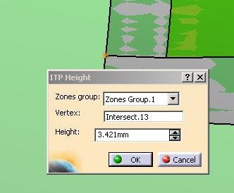
(You can find out the value by measuring the distance between the point and the solid you have generated previously).
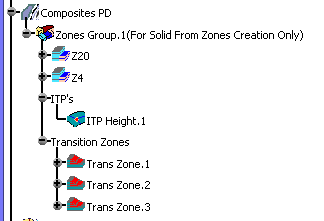
The IPT is displayed in the 3D view and created in the specification tree under the ITP'S node. They are displayed in the 3D view and created in the specification tree under the ITP'S node:
-
The solid needs to be updated.
See Updating the Solid for more information.
 |
Refer to Generative Shape Design & Optimizer User's Guide for more information.
![]()