- Point Modification Parameters
(accessible through
 ,
then
,
then  )
) - Area Modification Parameters
(accessible through
,
then
 )
) - PP Word
Modification Parameters (accessible through
,
then
 )
) - Translation Parameters
(accessible through
,
then
 )
) - Rotation Parameters
(accessible through
,
then
 )
) - Connection Parameters
(accessible through
,
then
 )
) - Change Approach and Retract Parameters
(accessible through
,
then
 )
) - Split
on Collision Points parameters (accessible through
 )
) - Check Tool Length
Parameters (accessible through
 )
) - Create
Geometries Parameters (accessible through
 )
)
Point Modification Parameters
Offers icons corresponding to different selection options.
Offers icons to cut or modify the points.
|
|
cuts points. |
|
|
validates the modification. |
x,y,z
Enter the new coordinates of the selected point.
Accessible in the 3D Viewer. Lets you:
- Pull the arrow to draw the selected point to its new position.
- Use its contextual menu to select the translation
direction of the selected point:
Last polyline is a line created between the previous point and the point selected,
Next polyline is a line created between the next point and the point selected.
- Or double-click the word Distance and enter the distance in the box.
Area Modification Parameters
-
 lets you translate the area selected,
 -
 lets you cut the area selected,
 -
 lets you modify the feedrate of the tool path, either locally or
globally:
lets you modify the feedrate of the tool path, either locally or
globally:
You can choose a new feedrate type:
If the feedrate type is local, you can enter its value:
-
 lets you define the area to modify by one point,
 -
 lets you define the area to modify by two points,
 -
 lets you define the area to modify by a contour,
 -
 lets you define the area to modify by
a polyline,
lets you define the area to modify by
a polyline, -
 lets you select collisions points,
 -
 lets you swap the selection,
 -
 lets you choose the selection options:
 - Distance: Accessible in the 3D Viewer. Lets you:
- Pull the arrow to draw the selected area of the tool path to its new position.w the selected area of the tool path to its new position.
- Use its contextual menu to select the translation direction of the selected area of the tool path.
- Or double-click the word Distance and enter the distance in the box.
PP Word Modification Parameters
-
 lets you
select the previous PP Word,
lets you
select the previous PP Word, -
 lets you
select the next PP Word,
lets you
select the next PP Word, -
 lets you
insert a new PP Word in the tool path
lets you
insert a new PP Word in the tool path -
 lets you delete a PP Word,
 -
 lets you
edit a PP Word.
lets you
edit a PP Word.
Translation Parameters
Accessible in the 3D Viewer. Lets you:
- Pull the arrow to draw the selected area of the tool path to its new position.
- Use its contextual menu to select the translation direction of the
selected area of the tool path.
- Or double-click the word Distance and enter the distance in the box.
Rotation Parameters
Accessible in the 3D Viewer. Lets you:
- Pull the arrow to draw the selected area of the tool path to its new position.
- Use its contextual menu to select the rotation axis of the
selected area of the tool path:
- Or double-click the word Angle and enter the angle in the box
Connection Parameters
Selection
Offers icons corresponding to different selection options.
|
|
Multi-selection: click this icon and pick several points one by one. |
|
|
Selection by sweep: click this icon, place the cursor over one point and drag
the mouse. The points under the mouse path are selected. |
|
|
Selection between two points: click
this icon, pick a first point, then a second point. All the points between those two points are selected. |
|
|
The two points must belong to the same tool path. |
|
|
Selection by polyline: click this icon, draw a polyline around the points you
want to select. The points inside this polyline are selected. |
|
|
Reverses the current selection. |
|
|
Resets all selections. |
Connection mode
|
|
Connects points directly |
|
|
Connects points through a plane |
|
|
Connects points through the safety plane of the operation. |
Defines the distance the tool will rise to.
Available when a plane is required. Lets you define the plane through a point and a normal. The connection will go through the point in the plane.
Change Approach and Retract Parameters
Lets you choose the type of the path you want to delete:
- Approach
- Retract
- Linking passes
- Between paths
You can select several types.
The action takes the whole tool path into account.
Remove from area inside polygon
The action takes only the selected portion of the tool path into account.
You select this portion by drawing a polygon on the tool path.
Selection
Offers icons corresponding to different selection options.
|
|
Multi-selection: click this icon and pick several points one by one. |
|
|
Selection by sweep: click this icon, place the cursor over one point and drag
the mouse. The points under the mouse path are selected. |
|
|
Selection between two points: click
this icon, pick a first point, then a second point. All the points between those two points are selected. |
|
|
The two points must belong to the same tool path. |
|
|
Selection by polyline: click this icon, draw a polyline around the points you
want to select. The points inside this polyline are selected. |
|
|
Reverses the current selection. |
|
|
Resets all selections. |
Apply
Lets you define the domain of application: either the whole tool path or a portion selected with Selection.
Approach/Retract
The tool moves along the tool axis for a given Length.
No approach/retract.
BackThe tool doubles back like an arrow above the cutting tool path.
You can either define this type with Cartesian coordinates (Distance
and Height) or
Polar coordinates (Angle and Radius).
The tool moves towards/away from the part in an arc.
You can choose to compute the plane in which the tool moves either
Automatically or
Manually.
The parameters that you can set are:
- the Length,
- the Angle
- the Radius
- the Normal vector to plane.
The tool moves across the diagonal of an imaginary box, either in a
straight line or in a curve (Linking
mode).
The Length is the distance that the tool will move in once it has
crossed the box.
The box is defined by three distance values:
- the distance along the tangent,
- the distance along the tool axis (can be a negative value) ,
- the distance along the normal axis,
- The direction of the box diagonal is defined by whether you want to
use the normal to the left or
the right of the end of the tool path. Left or right of the
Side of normal axis is determined by looking
along the tool path in the direction of the approach/retract.
Split on Collision Points parameters
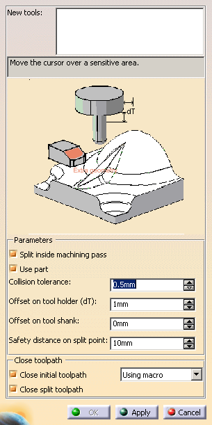
Allows you to add additional geometry to the part in the operation where the tool path was computed. Additional geometry may be a face or a clamp that you would rather avoid using in the computation and that is not defined in the operation
Allows the Split on Collision Points command to split a tool path between an approach and a retract motion (i.e. inside a machining pass).
Check this option to use the part you defined in the operation to compute the collision points.
Discretization distance to check for collision between the tool and the part.
Safety distance for the tool holder radius to avoid collision between the holder and the part.
Safety distance for the tool holder length to avoid collision between the holder and the part.Safety distance on split point
Defines the safety distance required on the first or last collision point to insert a collision free macro.
Example:
The collision area is in red.
After the split, the red area will disappear. But if you add a circular
macro for retract, the retract movement is in collision.
The
Safety distance on split point will cut the tool patch before
the last or the first collision free point to ensure that the retract or
approach macro will be collision free.
Close initial tool path and Close split tool path
Lets you close automatically the tool paths resulting
from the Split on Collision Points command.
If those check boxes
are not selected, you will have to close them
manually.
The split tool path is closed by adding
retract and approach macros while there are two methods to close the initial tool path automatically:
- using a macro: collision free approach macro and optimized
retract macros are added.
They are read from the initial operation.
If this is not possible (due to collisions), a Back macro will be added for the approach, and a Along tool axis macro will be added for the retract. - following the part: no retract nor approach macro is added and the tool path that is computed follows the part.
Example:
The collision area is in red:
The tool path has been split:
It is closed using macros:
or following the part:
Check Tool Length Parameters
Extra geometry
Allows you to add additional geometry to the part in the operation where the tool path was computed. Additional geometry may be a face or a clamp that you would rather avoid using in the computation and that is not defined in the operation
Use part
Check this option to use the part you defined in the operation to compute the collision points.
Collision tolerance
Discretization distance to check for collision between the tool and the part.
Offset on tool holder radius (dR)
Safety distance for the tool holder radius to avoid collision between the holder and the part.
Offset on tool length (dL)
Safety distance for the tool holder length to avoid collision between the holder and the part.Create Geometries Parameters
Defines the partbody of the geometrical set where the geometry will be created.
-
 lets you select the first point of the tool path.
 -
 lets you select the last point of the tool path.
 -
 lets you select all the points between the first point of the tool path and
the point picked.
lets you select all the points between the first point of the tool path and
the point picked. -
 lets you select all the points between the point picked and the last point
of the tool path.
lets you select all the points between the point picked and the last point
of the tool path. -
 lets you select all the points between two points picked.
 -
 lets you select all the points of the tool path.
You can also pick one point on the tool path.
Previsualization
By default, the Previsualization option is activated, i.e. the element of the type selected below is visualized. You can deselect this option. However, the points of the tool path are always visualized.
|
|
If you want to only visualize the geometry, do not push the Apply button since it would create the elements of the type selected. |
Type
Lets you select the type of elements you want to visualize or to create.
- Points: Creates points.
- Areas: Available if the type Points is selected, and if several points of the tool path are selected. Creates a join of lines from the portions of path selected.
- Axes: Creates tool axes (as points and lines).
- Tools: Creates tools (as revolves).
Apply becomes available once you have selected a
Destination.
It creates the elements of the type you have selected.
Select an area and a type of elements to create, click Apply, then repeat
these steps
to create elements on several areas.
Close
Exits the action. The elements created by Apply are not erased.