 |
This task explains how to generate a shell expansion drawing. This drawing
is generated by expanding the shell plate surfaces in the transverse
direction. A shell expansion drawing is used for checking dimensioning, topology, and
structural integrity of the shell plates. It verifies the seams, butts,
and internal hull structure of the shell plating.
Note: Beams and stiffeners (other than shell stiffeners)
having limits as shell plates, are excluded from the shell expansion
drawing.
Warning: There is no associativity maintained between the
shell expansion drawing and the design model. Therefore, you
cannot update of the shell expansion drawing. |

|
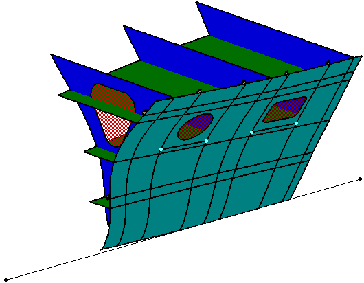
1. |
Create a
structure system. The image below shows a Portside shell with openings and
transverse and longitudinal stiffeners. Draw a reference line in the X
direction. Make sure that this is a straight line and is parallel to the center line of the ship.
This line is the curve from which the expansion parameters are computed.
In effect, it determines the position of the expanded plate.
 |
| |
2. |
Click the
Shell Expansion drawing
button  to display the
Shell Expansion dialog box. to display the
Shell Expansion dialog box.Note: To create the
shell expansion drawing of the SFD and SDD system, the
Shell Expansion drawing
command from Structure Functional Design workbench and Structure Detail
Design workbench should be used respectively.
The entries are
explained below:
 |
| |
3. |
Shell Plates:
Select the shell plates you want to expand. The name of the selected
shell is displayed. You can also select more than one shell plate. Click
the Element List button  to view the list of selected elements. You can
replace and remove the elements in the list. to view the list of selected elements. You can
replace and remove the elements in the list. |
| |
4. |
Reference:
Select a straight line in the X direction as the reference.
Note: The reference must be a straight line. There can be
only one reference element. |
| |
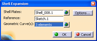
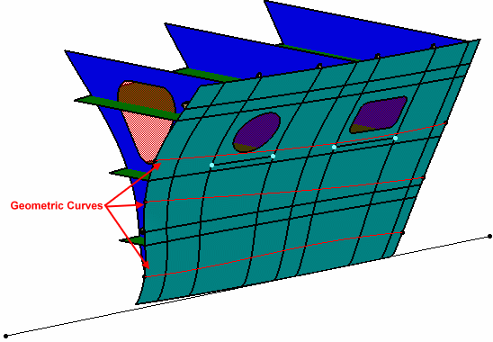
5. |
Geometric Curve(s): Optionally,
select the curves on the shell plates.
These curves are specific Hull Form related curves. For example, Flat of
Side curve is a curve that limits the flat surface and the curved
surface of the Hull Form.
 |
| |
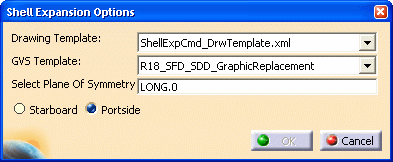
6. |
Click the Options button to
display the Shell Expansion Options dialog box. The entries are
explained below:
 |
| |
7. |
Drawing Template: Select the
drawing template (.xml file), which defines the sheet format, view
position, and
view scale of the drawing. By default, ShellExpCmd_DrwTemplate.xml file is
selected. You can select another file by selecting More in the list. |
| |
8. |
GVS Template: Select the
Generative View Style (GVS) file,
which defines the graphical replacement of the structural elements.
The sample drawing (ShellExpCmd_DrwTemplate.xml) and GVS
templates (Structure_GVS.xml) are located in
the following folder:
.../OS/resources/standard/generativeparameters |
| |
9. |
Select Plane of Symmetry: Select a
plane, which is symmetrical to the selected shell plates. By default,
LONG.0 is selected. This plane is used as a border between the
starboard and portside shell plates. You can select another plane in
your 3-D design. Note: If the shell plate is not split at the
selected plane, the shell expansion engine internally splits it to
generate the shell expansion drawing from one of the two split plates. |
| |
10. |
Starboard/Portside: Select the
side of the ship, from which the expansion drawing is to be generated.
This option determines the graphic properties of elements, other than
shell plates (for example, stiffeners, plates intersecting shell plate)
in the expansion drawing. Note: A split plate lying on the opposite
side of the user option (Starboard/Portside) is excluded right from the
beginning. It is not expanded. |
|
11. |
Click OK to close the
Shell
Expansion Options dialog box. Click OK in the Shell Expansion dialog
box. |
| |
|
The shell expansion drawing is
generated, as shown in the image below.
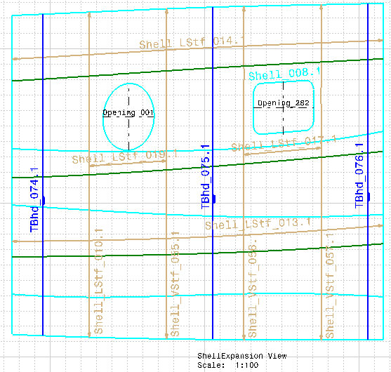
The stiffeners are generated
with arrows at extremities. The graphic properties, such as line type,
thickness, and color are read from the GVS file. The drawing shows alpha
numeric information and symbolization. |
 |
|
In the Knowledge Base
About a message which appears while creating a shell expansion drawing
from the shell plate |
|
|
|
|