|
This task explains you how to create scallops
on the 3D axis and edge of the plates and stiffeners.
You can create scallop on axis using the following modes:
|
 |
Scallops enable easy assembling of plates connected to other plates.
It also helps in performing the welding operation properly and provides
structure stiffness. The objective of Scallop on Axis command is to make the scallop creation
much quicker compared to a manual approach. |
 |
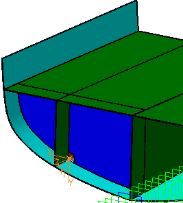
Create Scallop Using 3D Axis Mode
|
|
|
-
Click Scallop
on 3D Axis
 in the
Detailing Tools toolbar. in the
Detailing Tools toolbar.
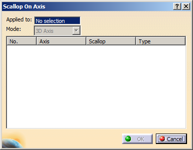
| The
Scallop on Axis
dialog box appears. |
 |
-
In the Applied to box, select the plate on
which you want to create scallop.
-
In the Mode list, select 3D Axis.
-
Right-click in the dialog box and
select Define Axis.
The Axis System Definition dialog box appears.
-
Create an axis system:
- In the Axis
system type list, select Standard.
- In the Origin box, select an
existing point or create a new point using the contextual
command.
 |
The point must lie on the molded surface. |
- Select directions for X, Y and Z
axes.
- Click OK.
The axis system and the scallop is created. The name of the
axis system and the name of the scallop appear in the Axis
and Scallop columns respectively. The scallop created
in the last session is displayed. If the repository is empty, a
Round scallop is created by default.
|
-
Define the scallop parameters, as required.
- Select the required row.
- Right-click the row and select Define Scallop.
| The Scallop Parameters dialog box appears. |
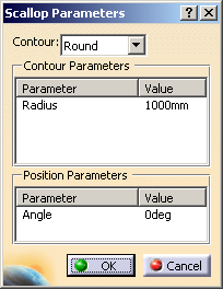 |
- In the Contour list, select one of the
following contour types:
- In the Contour Parameters area, the parameter
and the value of the contour are listed.
You can edit the value by double-clicking it.
- In the Position Parameters area, the
parameter and the value of the position orientation are
listed.
You can edit the angle value by double-clicking it.
- Click OK to return to the Scallop
dialog box.
The scallop parameters are defined.
|
-
Click OK in the
Scallop on Axis
dialog box.
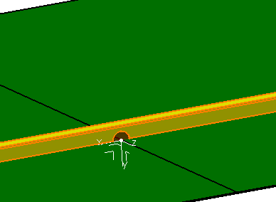
The element (identified as Scallop Contour) is added to the
specification tree in the OpeningSets.x node under the
Opening sub-node.
|
|
|
|
|
|
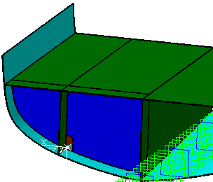
Create Scallop Using Edge Mode
|
|
|
-
Click Scallop on 3D Axis
.
| The
Scallop on Axis
dialog box appears. |
-
In the Applied to box, select a plate or a
stiffener on which you want to create scallop.
-
In the Mode list, select Edge.
-
Right-click in the dialog box and select Define
Intersection.
-
Select the edge of plate or stiffener and a reference
plane intersecting the selected edge.
|
|
The intersecting point must lie on the molded
surface. |
|
The axis system and the scallop is created. The name of the
axis system and the name of the scallop appear in the Axis
and Scallop columns respectively. The scallop created
in the last session is displayed. If the repository is empty, a
Round scallop is created by default.
|
-
Define the scallop parameters, as required. Refer to
step 6. in the above task.
|
The scallop parameters are defined.
|
-
Click OK in the
Scallop on Axis
dialog box.
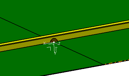
The element (identified as Scallop Contour) is added to the
specification tree.
|
|
|
- You can visualize the scallop representation in the graphic
replacement of the plates in SideView and
AnyView. It will appear similar to the opening in the
drawing.
- To edit or delete the scallops on axis, perform step 1 and 2. The
dialog box displays the existing scallop. Right-click and select
Define Scallop or Delete Scallop to edit or delete the
scallop respectively.
|
|
 |