|
|
This feature aids the designer in identifying and viewing generic relationships between objects, and is particularly useful for viewing relationships between objects coming from different applications. The different types of relationship are organized under tab pages:
The tab pages available and the relationships shown in each tab page are controlled by the object selected (the current object). |
|
|
|
This tasks shows you how to use the Object Relationships command. |
|
|
|
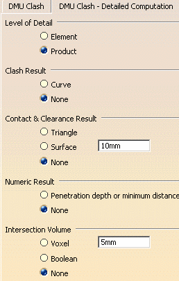
To reduce unnecessary computer processing time when viewing object
relations in the Interference tab you will need to make some changes in
the Tools > Options settings.
Go to Tools > Options, select Digital Mockup, DMU Space Analysis then click the DMU Clash - Detailed Computation tab. Change the settings if necessary for Level of Detail, Clash Result and Numeric Result to match those shown below. Note: The DMU Space Analysis product must be installed to access DMU Clash option pages.
|
|
|
|
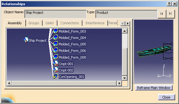
1. | With your product
open, click the Object Relationships
The Relationships dialog box opens. In the example, below, the assembly tree expands at the Product level to show the related preliminary design objects. The Assembly tab displays up to three levels: parent, current object and children. In the preview pane, you can zoom and rotate the image just like in the geometry area. The Reframe Main Window button updates the geometry area with the preview viewpoint.
|
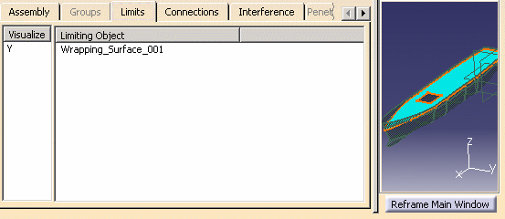
| 2. | Double-click an
object to view its relationships.
The various tabs will become active only when the selected object supports that kind of relationship, for example, if it is a type of object that can have limits. In the example below, a deck has been selected to view Limits. In the Visualize column, toggle the Y/N to show or hide an object in the preview pane.
|
|
|
|
An object can be
selected from the geometry area, the specifications tree, or from the
assembly tree or via the preview pane in the dialog box. In any tab page:
|
|
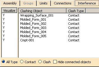
| 3. | Click the
Interference tab to display objects that clash (intersect) with the
current object. You can filter the list by selecting All Type, Contact
or Clash.
Note: Only basic geometric objects, not assemblies, can be analyzed for interferences.
Select the Hide connected objects check box to hide objects with known connections (i.e. listed in the Connections tab) and not display them in the Interference tab list. |
|
| 4. | Click
the Connections tab to display connected objects.
Take some time to experiment with the several combinations of tab selection, object type and filter selections and observe the available information. |
|
| 5. | Click Close when done. | |
|
|
||