 |
In this task, you will learn
how to create a multi line logical view. |
 |
To access the logical mode, you need to apply these settings:
- Go to Tools > Options > Drafting > Administration
tab. Clear the Prevent generative view style usage check
box.
- Go to Tools > Options > Drafting > View tab. Select
the Select body in assembly check box.
In addition, to get the multi line graphic result, ensure that the
following environment variable is set:
set SFM_DFT_MULTIRESULT=1
|
|
|
View Types
|
 |
When you generate graphic replacement for structure objects, the
projected objects give a 2D result on the basis of the view type. The
available view types are: Near Side, Far Side, and Across Side. The
display and type of the resulting drawing is controlled by Near Side,
Far Side, and Across Side parameters in the GVS file. For more
information, see Near Side, Far Side, and Across Side View Types.
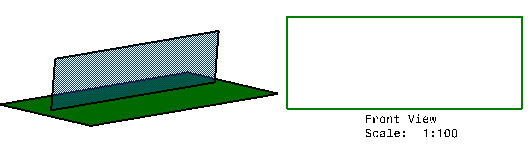
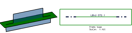
- An object is in Near Side when its 3D geometry is fully viewed
from the projection point. Near Side objects are hidden when their
graphic replacement is generated. The images below show Near Side
objects in 3D and their corresponding 2D drawing.
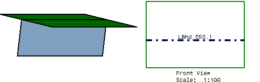
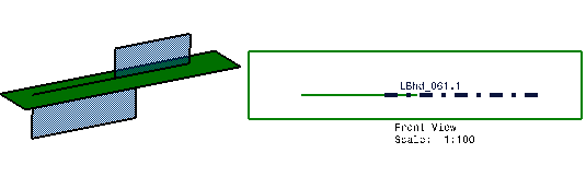
- An object is in Far Side when its 3D geometry is fully hidden
from the projection point. The images below show Far Side objects in
3D and their corresponding 2D drawing.
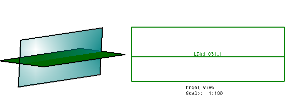
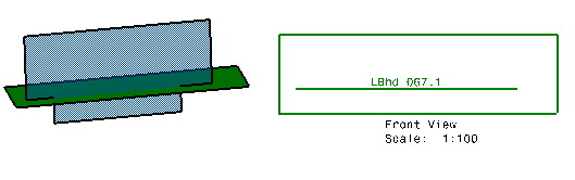
- An object is in Across Side when its 3D geometry is crossing a
reference object. The images below show Across Side objects in 3D
and their corresponding 2D drawing.
 |
|
|
Multi Line Logical View
|
 |
-
Open a CATPart document.
-
Create a multi line scenario where structure objects
belong to more than one view type. Define a new drawing sheet.
-
Click Advanced Front View  in the
Views
toolbar. in the
Views
toolbar.
The View Parameters dialog box is
displayed.
-
Enter the scale and select
the GVS file. Click OK.
-
Select the structure Superobject in the 3D model.
A warning message is displayed. Click OK and continue
with the view creation.
-
Select the plane of projection.
-
Click in the drawing document to generate the
logical view. The logical view shows the selected object and objects
logically connected to it.
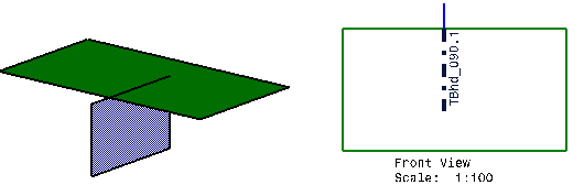
The images below show the 3D models and their
corresponding logical
views for different multi line scenarios.
|