Creating a Logical View

In this task, you will learn how to create a logical view.
The logical view is not a standard mode of generating views. It is available in structure applications only. It filters out the objects that are not relevant to the view and extracts only the selected object and objects connected logically to it.
To access this mode, you need to apply these settings:
  • Go to Tools > Options > Drafting > Administration tab. Clear the Prevent generative view style usage check box.
  • Go to Tools > Options > Drafting > View tab. Select the Select body in assembly check box.
 

Creating a Logical View

  1. Open the CATPart document containing your functional system or design unit. Define a new drawing sheet.

  2. Click Advanced Front View  in the Views toolbar.

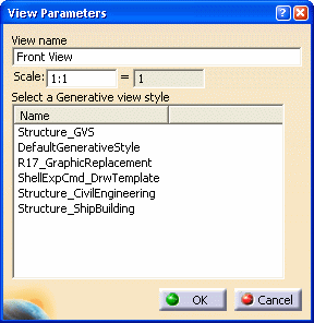
  3. The View Parameters dialog box is displayed.

  4. Enter the scale and select the GVS file. Click OK.

  5. Select the structure Superobject in the 3D model. For example, SuperPlate, SuperProfile (Stiffener, Beam etc.) In this example, TBhd_C51_1 is selected.

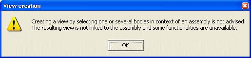
  6. A warning message is displayed. Click OK and continue with the view creation.

  7. Extract the support of the selected object. In this example, the grid plane systems DECK and LONG are selected.

  8. Select the plane of projection. In the example, plane YZ is selected.

  9. Click in the drawing document to generate the logical view. The logical view shows the selected object and objects logically connected to it.

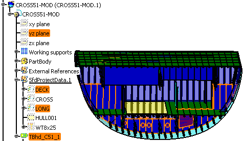
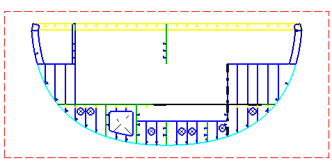
  10. The images below show the 3D model and the logical view extracted from the 3D model.

 
3D model Logical view