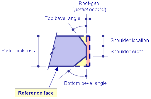
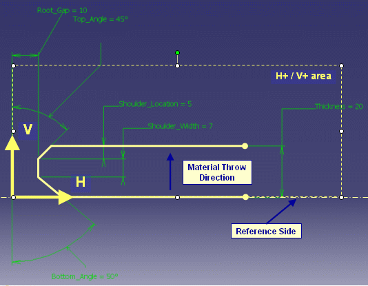
The main characteristics of a plate edge that is prepared for welding are shown below:
A root gap is the distance between two plates to be joined to improve penetration of weld and increase quality and strength of weld joints. The root gap can be considered as a negative margin that needs to be applied to the plate contour.
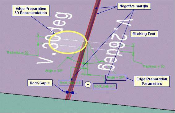
The figure below shows how the edge preparation characteristics of a joining activity could be shown during the interactive session.
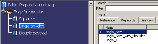
Standard default edge preparation symbolic parametric sketches are provided
in a catalog of User Defined Features (UDFs). It is found at the following
location:
..\OS\startup\startup\FeatureCatalogs\Edge_Preparation.catalog
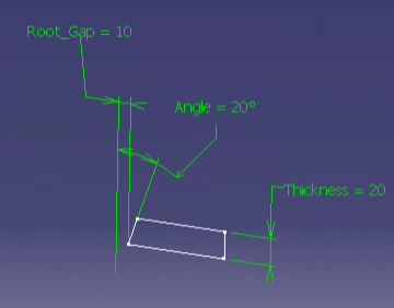
Here is a sample parametric sketch of a V Bevel edge preparation:
A quick way to create your own edge preparation UDFs is to start from an existing one. In any case, standard conventions must be respected:
You must set parameters that are to be displayed in 3D.
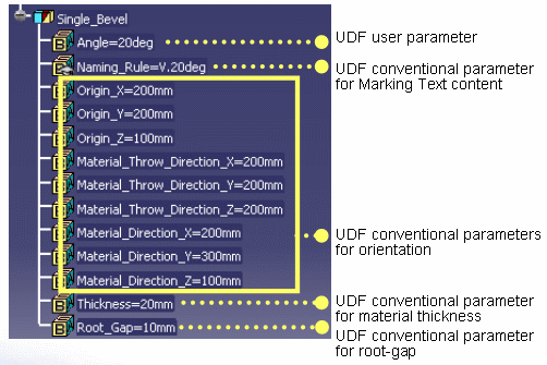
Edge preparation is described through a User Defined Feature exposing:
A marking text is associated to the edge preparation. Its content is related to the Naming_Rule published parameter.
A negative margin is associated to the edge preparation. Its value is related to the Root_Gap value.
Display the sketch constraint in Part.
Right click on constraint in tree and select Add Display.
Various display modes are available: value only, name only, both name and
value, with or without a leader.
Two kinds of parameters must be published:
Marking texts are specific to each shipyard. They have their own conventions to put information on the plate on shape. It is up to administrator to define the content of each text associated to edge preparation. This can be done either by creating new edge preparation UDFs or by editing each UDF part contained in the catalog and modifying the content of the Naming_Rule parameter.
Note that the content of the text for Single_Bevel is different from the other in the catalog as it demonstrates the capability to associate parameter value to the marking text.
To display the parameters and constraints of the UDFs, select the Parameters of features and constraints check box under the Display in Geometry Area that is part of the Part Infrastructure tab in Tools > Options > Infrastructure.
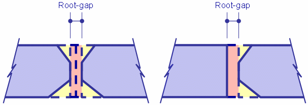
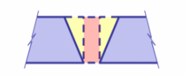
You need to check that correct edge preparation configuration has been provided for performing welding process. As edge preparation activity is performed separately on each single plate or profile with a given workshop position, you must check that plates or shapes positioned together when they are welded do not show mismatches between their edge preparation.
Figure below shows mismatch between edge preparations at welding stage.
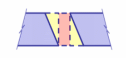
Figure below shows correct edge preparation configuration.
To check that a generated edge preparation is correct you can check the following points.