The procedure describes how to create a 3D state object. A 3D state object can consist of individual manufacturing positions or it can include other 3D states. As is the case with manufacturing positions, 3D states are defined for parts and resources assigned to a process. These states can be applied during process verification or simulation to show the proper state of products and resources in the 3D viewer.
States consist of existing manufacturing positions or other named 3D states that have already been defined. Therefore, it is necessary that manufacturing positions or other 3D states have been already been created for the selected part or resource before creating a 3D state object.
Click Create State
 .
.-
Select a part or resource in the PPR tree for which a named state is to be created.
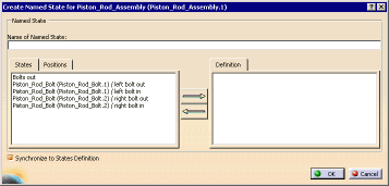
The part or resource must have a position or named state already created for it previously. The Create Named State for Selected_Part_or_Resource dialog box appears. The named states and positions previously created for the part or resource appear. 

Positions can only be used in states on the same product or resource to which the position belongs. States can be used in states of any part of the product or resource to which the state belongs. For instance, suppose you have an assembly (such as the Piston Rod Assembly) that has positions for specific parts (such as the bolts). You can use the positions for the bolts to create states for associated with the bolts (as was done in the example below), but you cannot use the positions for the bolts to create directly states for the rod assembly. Instead, use the states for the bolts. -
In the Name of Named State field, enter a name for the state.
-
Select one or more states and click the right arrow.
The state or position appears in the Definition area. If the state alters the current position of the geometry, the geometry is synchronized to the state definition as long as the Synchronize to State Definition check box is selected (it is selected by default). If you do not want to see any change in the 3D geometry while you are defining the state, clear the check box. -
Once you have defined the state, click OK.
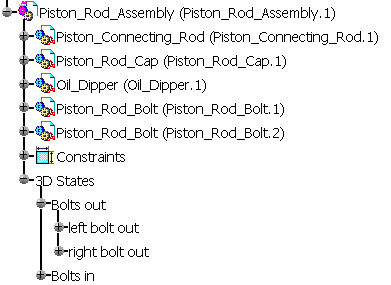
The state appears in the 3D State node under the selected part. 