This task shows you how to create a flanged cutout by specifying the punch geometrical parameters.
Open the
NEWStamping8.CATPart document.
If you use the Aerospace SheetMetal Design workbench, open the
Aero_Stamping8.CATPart document.
-
Click Flanged Cutout
 .
.
-
Select a profile.
The Flanged Cutout Definition dialog box is displayed, providing default values. 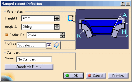
-
Change the value in the different fields, if needed:
-
Height H: use one of the following options to compute the height of the flanged cutout.
-
 : computes height from the bottom of the thickness to the
inner boundary edge of the flanged cutout
 -
 : computes height from the top of the thickness to the
outer boundary edge of the flanged cutout
-
-
Angle A
-
Radius R
-
-
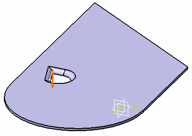
Click Preview to visualize the flanged cutout.
-
Click OK to validate.
The flanged cutout (identified as Flanged Cutout.xxx) is created and the specification tree is updated accordingly. 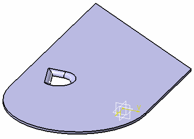
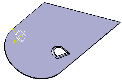

You can use 0 as the Radius value to deactivate the Radius R value, and to create the flanged cutout without a fillet. 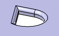
Note that if you create a flanged cutout from a sketch that is not tangent continuous, you cannot design any other feature on it (such as bend, cutout, hole). 
Please refer to the Customizing Standard Files chapter to define the Standards Files.
![]()