-
Click XYZ Automatic Planar Sections
 in the Scan Creation toolbar, and select the
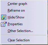
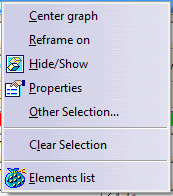
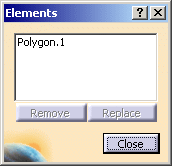
Element to cut.
in the Scan Creation toolbar, and select the
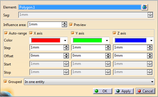
Element to cut. If some elements selected are volumes or surfaces, they are tessellated. Sag becomes available. Edit it if necessary.
-
Define the Influence area according to your needs.
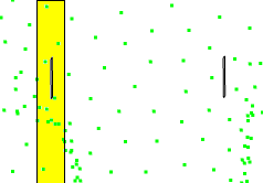
For clouds of points, the Influence area parameter defines a computation area around the cutting planes: when the points are not dense, a cutting plane (black line) may be unable to intersect the points. The Influence area is the area shown in yellow that contains the points considered to intersect the cutting plane.
-
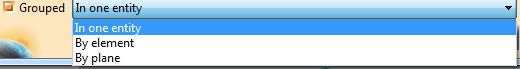
Select the axes to take into account to compute the planar sections.
They refer to the current axis system, either the default standard axis system or any axis system you have set as current.
-
Select or clear Auto-range, according to your needs:
- By default, Auto-range is selected, and the Start and Stop values are adjusted automatically for each direction, depending on the elements selected.
- Clear Auto-range to input your own Start and Stop values, to create the planar sections only on a portion of the selected elements.
Define the Offset from the axis system origin along each axis, and the Step between planar sections.
-
For each axis, select the Color to apply to the planar sections created in that direction from the list.
The cutting planes in each direction are displayed in the graphic area.

-
When you are satisfied, select an output option
and click OK to validate and create the planar sections as explained in Creating Planar Sections.
![]()