- Before You Begin with Replace command
- What is Replace Command?
- When do you use the Replace Operation?
- What Type of Elements it can be used on?
- What Type of Elements are Impacted by Replace Operation?
- What Checks are Performed Before the Replace Operation?
- Accessing the Replace command
- More on Replacing Elements
Before You Begin with Replace command
Based on the use of the function and the context in which it is used, the function is explicitly available in two different commands,
- Replace... command
- Replace Component command
Using Replace...command
The Replace command is Mechanical Modeler command. It is used to replace/substitute one feature with an another feature within a Part context.
Using the Replace Component command
The Replace Component command is Product Structure
command. It is used to replace/substitute one design document within an
another design document in a Product context e.g. Products,
Part or other pointed documents in an assembly.
For more information about Replace Component Command, See
Assembly Design user's Guide: Assembly Components - Replacing
Components.
What is Replace command?
Using the Replace operation on a feature and choosing another one to replace it, means that all the features that referenced the replaced feature, will reference the replacing feature at the end of the operation. However, certain checks are done before the replace operation is performed in order to ensure it will not compromise design consistency.
When do you use the Replace Operation?
The Replace operation may be useful when a modification occurs late in the design. When a feature is replaced, the whole geometry based onto the feature that is replaced is updated according to the new specifications coming from the replacing feature. Thus it helps you in quick design modifications.
What Type of Elements it can be used on?
The Replace command is used to replace the geometrical elements. It can be used to replace the elements such as,
- Reference Elements- Lines, Planes and Points
- Wireframe Elements- Curves and Sketches
- Surface Elements- Surfaces and Volumes
- Solids Elements- Bodies only
Note: The solid features such as Pad, Fillet, Draft, etc constitute to form a body element which cannot be individually replaced.
What Type of Elements are Impacted by Replace Operation?
Launching the Replace operation on a feature impacts features that are based on it :
- The features that reference the replaced feature as a whole (e.g. a Line that references a Point)
- The features that reference a sub element of the geometry of the replaced feature (e.g. an EdgeFillet that references the Edge of a Surface).
Therefore, the replace operation impacts the child features. It does not affect the parent features of the replaced feature.
By selecting the option Do replace only for elements situated after the In Work Object in Tools > Options > Infrastructure > 3D Shape Infrastructure > General tab > Replace you can choose to limit the impact of the replace operation to only the features located after In Work Object in the specification tree.

In case of solid bodies, when a replace operation is performed on a body, the elements which are referencing the body gets impacted. But the elements which are referencing the solid feature inside the replaced body are not impacted.
What Checks are Performed Before the Replace Operation?
When you replace a feature with an another feature, the replace operation is performed if the following checks are satisfied:
- The feature to replace is one of the elements stated in What Type of Elements it can be used on?
- The replace operation do not lead to on update cycle. In case of designs in ordered sets (OGS or Bodies), order and absorption concepts are respected. To know more about order and absorption concept, see Creating Bodies in a Hybrid Design Environment.
- The impacted elements (child elements) are not located before the Work In Object if the replace setting is selected.
Based on the above check results the replace operations can be fully or partially executed or blocked. An information dialog box is displayed to update you on operation status in case the replace leads to inconsistencies.
Accessing the Replace command
The command can be accessed by Right-clicking the element to be replaced and select Replace... from the contextual menu.
Lets now see the different options available in the replace capability.
- Right-click the element and choose the
Replace... in contextual item.
The Replace dialog box appears.
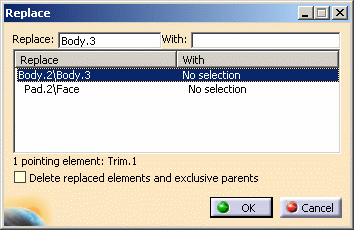
Replace: Select the element to be replaced.
With : Select the replacing element. - By clicking OK, the design is updated according to the new specifications coming from the replacing elements.
- If the Delete replaced elements and exclusive parents option is selected in the Replace dialog box, then after replacing the geometries by others, the replaced geometry will be deleted in the end.
- If there is a unique solution to replace the geometry, it is
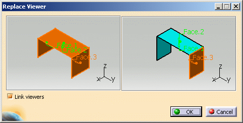
directly replaced and the Replace Viewer dialog
box is not displayed. If there is no unique solution to replace the
geometry, then the Replace Viewer dialog box helps
you to make the choice between multiple solutions.
In the example below, select the corresponding faces for Face.1, Face.2 and Face.3 in right graphic window to get the appropriate solution.
| Element | Before | Replace Action | After | Remarks |
| Replacing Curve |
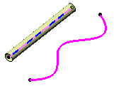 |
Replace: Blue curve with: Pink Curve |
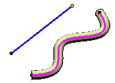 |
By replacing the parent element the feature gets updated. |
| Replacing Surface |
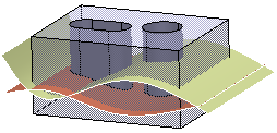 |
Replace: Brown surface with: Yellow surface |
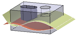 |
After replacing the brown surface, Yellow surface acts as new limiting element for the pocket and hole features inside the Pad. |
| Replacing Body |
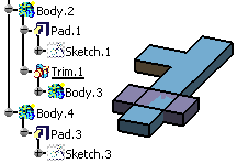 |
Replace: Body.3 with: Body.4 |
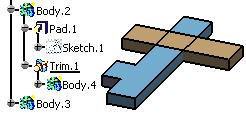 |
When replacing a body you need to select the replacing face in Replace Viewer window. Once the replacing face has been selected, a green arrow appears on it to confirm the orientation of the feature. |
| Replacing Sketch |
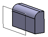 |
Replace: Sketch.1 with: Sketch.2 |
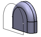 |
By replacing one sketch with another in Sketcher workbench, it does no impact on 2D. Only the 3D geometrical elements which uses the replaced 2D geometrical elements will be modified. |
To replace a face, you have a dedicated command Replace Face available in Part Design workbench. Refer to Creating Replace face Feature in the Part Design User's Guide.
More on Replacing Elements
- When you replace a Published element, a warning message is issued.
- Click Yes to replace the published element.
- Click No to cancel the operation and close the Replace dialog box.
- It is recommended to use Replace command on the updated elements.
- Replace command is used to replace elements, however it is not used to replace the features such as Pad, fillet of instance.
- You can only replace a body that is pointed by an Add feature
(Boolean Operation).
Refer to Adding Bodies in the Part Design User's Guide.
![]()