- Supported Activities
- Command Mapping
- Block Format
Supported Activities
Currently, the following V5 entities are supported in download and upload for the Kawasaki AS translator:
- Controller profiles (motion, accuracy, tool, and object frame)
- Motion activities (linear, joint, and circular motion types)
- Set IO activity
- Wait for IO activity
- Delay activity
- Spot Weld action
- Part Pick action
- Part Drop action
- Tool Pick action
- Tool Drop action
Command Mapping
This table displays the mapping between V5 entities and the Kawasaki AS commands, categorized as follows:
- Comments
- Controller Profiles and Configuration
- Tool, Object Frame offsets, and Tag Points
- Digital Signals and Delays
- Control Flow Statements
- Move Statements
- Robot Tool Statements
Block Format
Two formats are supported on all Kawasaki controllers (which include the C, D and E controllers): the Kawasaki AS language format and the Kawasaki block format. For upload, either format is read. For download, the default format is the AS language.
The following is an example of the Kawasaki AS format:
.PROGRAM bbb()
TOOL utool_1
SPEED 40 ALWAYS
ACCEL 100 ALWAYS
DECEL 100 ALWAYS
CP OFF
ACCURACY 0 ALWAYS
JMOVE t1
JAPPRO t1, 25
JDEPART 25
JMOVE t1
JMOVE t2
LMOVE t3
HOME
CALL proc_a
CALL proc_b
.END
The following is an example of the Kawasaki block format:
.PROGRAM proc_a()
JOINT SPEED9 ACCU1 TIMER1 TOOL3 WORK0 CLAMP1 (OFF,0,0,C) 2 (OFF,0,0,C) 3 (OFF,0,0,C) 4 (OFF,0,0,C) OX= WX=
#[34.131302,17.329000,6.235760,-99.103798,34.628201,101.019997] ;
JOINT SPEED9 ACCU1 TIMER1 TOOL1 WORK0 CLAMP1 (OFF,0,0,C) 2 (OFF,0,0,C) 3 (OFF,0,0,C) 4 (OFF,0,0,C) OX= WX=
#[19.223200,20.541700,18.259501,96.235001,71.779701,-109.260002] ;
.END
Note that in the block format case the speed, accuracy, timer, tool, and work are referenced as an index number. Control of peripheral devices and I/O signals is handled in the block format command via the CLAMP, OX, and WX values. Also, the joint values for the robot motion are provided in the block format. The key difference from AS being that all information required for each move is in the same block step. In the AS case speed, accuracy and I/O signals are all handled as separate command line arguments. Also for AS the robot motion target is typically stored as a variable.
In the block format case, more information is needed for SPEED, ACCU, TIMER, TOOL and WORK than just an index. The Kawasaki controller stores the index values in what is called an AUXDATA block, as shown in the following example:
 .AUXDATA
TOOL1  0.000 0.000 0.000 0.000 0.000 0.000
TOOL9 0.000 0.000 0.000 0.000 0.000 0.000
WORK1 0.000 0.000 0.000 0.000 0.000 0.000
WORK9 0.000 0.000 0.000 0.000  0.000 0.000
ACCUR 1.000 5.000 30.000 50.000
SPEED  10.000 20.000 30.000 40.000 50.000 60.000 70.000 80.000 90.000 100.000
TIMER 0.000 0.100 0.200 0.300 0.400 0.500 0.600 0.700 0.800 0.900
.END
During upload, in addition to parsing the block format, the translator parses the .AUXDATA values in either the program uploaded or in other programs with the .AS extension. If the .AUXDATA values are not found, default values are used.
Controller-specific Block Format
There are several variations of the block format, and each is supported in the Kawasaki translator. Default is determined using the parameters EndOfArmToolType and Controller shown in translator attributes table below. Default is AIRGUN with E controller.
C, D, E Controller for Handling or Air gun
JOINT SPEED9 ACCU1 TIMER0 TOOL1 WORK0 CLAMP1 (OFF,0,0,O) 2 (OFF,0,0,O) OX= WX=  #[0,0,0,0,0,0,0]
JOINT		: Joint ( motion ) Type
SPEED		: Speed	( from 0 to 9 )
ACCU		: Accuracy	( from 0 to 4 )
TIMER		: Timer	(from 0 to 9 )
TOOL		: Tool	( from 1 to 9 )
WORK		: Work	( from 0 to 9 and C )
CLAMP X(OFF,0,0,O)	: Clamp	CLAMP 1(2,3,4,5)
		1:Clamp Number  2:ON/OFF  3:WS  4:CC  5:O/C
OX		: OX Signal
WX		: WX Signal
#[0,0,0,0,0,0,0]: Position information (for each axes)
C Controller for Servo Gun
Weld position information (Servo Clamp: from 0 to 7) is added to the format of C Controller for Servo.
JOINT SPEED9 ACCU1 TIMER0 TOOL1 WORK0 CLAMP1 (ON,0,1,1) 2 (OFF,0,0,O) OX= WX= #[0,0,0,0,0,0,58.584]
JOINT		: Joint ( motion ) Type
SPEED		: Speed	( from 0 to 9 )
ACCU		: Accuracy	( from 0 to 4 )
TIMER		: Timer	(from 0 to 9 )
TOOL		: Tool	( from 1 to 9 )
WORK		: Work	( from 0 to 9 and C )
CLAMP X(OFF,0,0,O)	: Clamp	CLAMP 1(2,3,4,5)
		1:Clamp Number  2:ON/OFF  3:WS  4:CC 5 Weld position information: (Servo Clamp : from 0 to 7) (Others : O/C)
OX		: OX Signal
WX		: WX Signal
#[0,0,0,0,0,0,0]: Position information (for each axes)
D Controller for Servo Gun
Clamp information is added to the format of D Controller for Servo gun.
JOINT SPEED9 ACCU1 TIMER0 TOOL1 WORK0 CLAMP1 (ON,0,1,1) 2 (OFF,0,0,O) OX= WX= CL1=0.000,0.0,0.0,0.0,0.0  #[0,0,0,0,0,0,58.584]
JOINT		: Joint ( motion ) Type
SPEED		: Speed	( from 0 to 9 )
ACCU		: Accuracy	( from 0 to 4 )
TIMER		: Timer	(from 0 to 9 )
TOOL		: Tool	( from 1 to 9 )
WORK		: Work	( from 0 to 9 and C )
CLAMP X(OFF,0,0,O)	: Clamp	CLAMP 1(2,3,4,5)
		1:Clamp Number  2:ON/OFF  3:WS  4:CC 5:Weld position information (Servo Clamp : from 0 to 7) (Others : O/C)
OX		: OX Signal
WX		: WX Signal
CLn=0.000,0.0,0.0,0.0,0.0	: Clamp Information
		CL1=2,3,4,5,6
		1 Number that is assigned to the Servo Gun
		2 Pressure ( 3 below a decimal point, from 0.000 to 9.799 ) Unit : kN
		3 Clearance by the side of movable ( 1 below a decimal point, from 0.0 to 999.9 ) Unit : mm
		4 Clearance by the side of fixation ( 1 below a decimal point, from 0.0 to 999.9 ) Unit : mm
		5 Before a welding point clearance movable side ( 1 below a decimal point, from 0.0 to 999.9 ) Unit : mm
		6 Before a welding point clearance fixation side ( 1 below a decimal point, 0.0 to 999.9 ) Unit : mm
#[0,0,0,0,0,0,0]		: Position information (for each axes)
E Controller for Servo Gun
Two arguments are added in the Clamp information to the format of E Controller for Servo gun.
JOINT SPEED9 ACCU1 TIMER0 TOOL1 WORK0 CLAMP1 (ON,0,1,1) 2 (OFF,0,0,O) OX= WX= CL1=0.000,0.0,0.0,0.0,0.0,0.0,0.0  #[0,0,0,0,0,0,58.584]
JOINT		: Joint ( motion ) Type
SPEED		: Speed	( from 0 to 9 )
ACCU		: Accuracy	( from 0 to 4 )
TIMER		: Timer	(from 0 to 9 )
TOOL		: Tool	( from 1 to 9 )
WORK		: Work	( from 0 to 9 and C )
CLAMP X(OFF,0,0,O)	: Clamp	CLAMP 1(2,3,4,5)
		1:Clamp Number  2:ON/OFF  3:WS  4:CC 5: Weld position information (Servo Clamp : from 0 to 7) (Others : O/C)
OX		: OX Signal
WX		: WX Signal
CLn=0.000,0.0,0.0,0.0,0.0	: Clamp Information
		CL1=1,2,3,4,5
		1 Number that is assigned to the Servo Gun
		2 Pressure ( 3 below a decimal point, from 0.000 to 9.799 ) Unit : kN
		3 Clearance by the side of movable ( 1 below a decimal point, from 0.0 to 999.9 ) Unit : mm
		4 Clearance by the side of fixation ( 1 below a decimal point, from 0.0 to 999.9 ) Unit : mm
		5 Before a welding point clearance movable side ( 1 below a decimal point, from 0.0 to 999.9 ) Unit : mm
		6 Before a welding point clearance fixation side ( 1 below a decimal point, 0.0 to 999.9 ) Unit : mm
		7 After a welding point clearance movable side ( 1 below a decimal point, from 0.0 to 999.9 ) Unit : mm
		8 After a welding point clearance fixation side ( 1 below a decimal point, 0.0 to 999.9 ) Unit : mm
#[0,0,0,0,0,0,0]		: Position information (for each axes)
Block Format Attributes
| Attribute Type | Parameter Name (Tentative) | Value Type | Default Value | Usage | Possible values | Description |
| Device/Task/Activity | DownloadBlockFormat | Boolean | false | Download | false/true | If false, Download to general AS format. If true, download to Block format |
| Device | SpeedAbsTime | Boolean | false | Upload/Download | true/false | If false, speeds are defined only "%". If true, speeds are defined "mm/sec". "sec" and "%". |
| Device | OXWXNegative | Boolean | false | Upload/Download | true/false | If false, "OX=" and "WX=" are only available positive integer. If true, "OX=" and "WX=" are available negative integer |
| Device | OX_PreOutput | Boolean | true | Upload/Download | true/false | If true, V5 translates "OX=" as if OX.PREOUT SWTITCH=ON If false, V5 translates "OX=" as if OX.PREOUT SWTCH=OFF. |
| Device | NumberOfClamp | Integer | 2 | Download | 1/2/3/4 |
Define downloading format of CLAMP information1,
when no CLAMP_information1 attribute under robot
motion.
|
| Device | EndOfArmToolType | String | AIRGUN | Download | SERVOGUN/AIRGUN/HANDLING |
Define downloading format of CLAMP information1 and
CLAMP information2, when no CLAMP_information1/2 attribute under robot
motion.
|
| Device | Controller | String | E | Download | C/D/E |
Define downloading format of CLAMP information2,
when no CLAMP_information2 attribute under robot motion.
|
| Device | AUXDATA_SPEED | String |
10.000,20.000,30.000,40.000,50.000, 60.000,70.000,80.000,90.000,100.000 |
Download/Upload | 10 positive real CSV | Define SPEED levels when no SPEED0-9 motion profiles |
| Device | AUXDATA_ACCU | String | 1.000,10.000,50.000,100.000,1.000 | Download/Upload | 5 positive real CSV | Define ACCURACY levels in case Accuracy profiles' name is not ACCU0-ACCU4 |
| Device | AUXDATA_TIMER | String |
0.000,0.100,0.200,0.300,0.400,0.500, 0.600,0.700,0.800,0.900 |
Download/Upload | 10 positive real CSV |
Define TIMER levels
in case Robot delay activity's name is
not TIMER0-TIMER9.
|
| Activity Attribute | CLAMP_Information1 | String | - | Upload/Download | - | When uploading save CLAMP syntax. When downloading use for CLAMP syntax. |
| Activity Attribute | CLAMP_Information2 | String | - | Upload/Download | - | When uploading save CLAMP syntax. When downloading use for CLAMP syntax. |
Robot Block Motion Data
The motion type, speed, accuracy, tool, work, and target values from the block format are all uploaded to or downloaded from the robot motion activity.
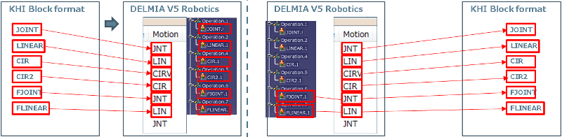
Block Motion Type
The following is an example of a JOINT motion type for Kawasaki block format:
JOINT SPEED9 ACCU1 TIMER0 TOOL1 WORK0 CLAMP1 (ON,0,1,1) 2 (OFF,0,0,O) OX= WX= CL1=0.000,0.0,0.0,0.0,0.0,0.0,0.0 #[0,0,0,0,0,0,58.584]
Other motion types and how they will be uploaded/downloaded is shown here:
Block SPEED
The following is an example of a SPEED value for Kawasaki block format:
JOINT SPEED9 ACCU1 TIMER0 TOOL1 WORK0 CLAMP1 (ON,0,1,1) 2 (OFF,0,0,O) OX= WX= CL1=0.000,0.0,0.0,0.0,0.0,0.0,0.0 #[0,0,0,0,0,0,58.584]
The SPEED index can be 0-9. If the SPEED values are declared in the .AUXDATA section of the program uploaded or in a .AS file in the same directory then those values will be used to set the motion profile speeds. Default values are shown here.
SPEED 10.000 20.000 30.000 40.000 50.000 60.000 70.000 80.000 90.000 100.000
If the parameter SpeedAbsTime is not set or is set to False then all speed values are in percent. If the parameter is True then SPEED0-5 are absolute mm/sec, SPEED6-7 are time seconds, SPEED8-9 are percent. During upload a motion profile will be created for each SPEED value found (i.e. SPEED0-9) and the type will be percent, absolute or time depending on the SpeedAbsTime parameter value. If no SPEED values are found then AUXDATA_SPEED parameter values will be used which are defaulted to 10,20,30,40,50,60,70,80,90,100. One value for each SPEED0-9 respectively.
For download, if SPEED0-9 motion profiles are used that name will be output to the block format regardless of values.
If no SPEED0-9 are used and SpeedAbsTime is False, the absolute or percent speed will be used to calculate the index as follows:
Percent =
Or,
Percent = < motion profile absolute speed>/*100
The index used is based on the AUXDATA_SPEED parameter values which default to 10,20,30,40,50,60,70,80,90,100. The percent value is always truncated so if it is less than 50 but greater than or equal to 40 then index 3 would be used. If a timed motion profile is used then translation will fail.
If no SPEED0-9 are used and SpeedAbsTime is True, SPEED0 is always output and a warning is displayed.
Block ACCU
The following is an example of a ACCU value for Kawasaki block format:
JOINT SPEED9 ACCU1 TIMER0 TOOL1 WORK0 CLAMP1 (ON,0,1,1) 2 (OFF,0,0,O) OX= WX= CL1=0.000,0.0,0.0,0.0,0.0,0.0,0.0 #[0,0,0,0,0,0,58.584]
The ACCU index can be 0-4. If the ACCU values are declared in the .AUXDATA section of the program uploaded or in a .AS file in the same directory then those values will be used to set the accuracy profile distance. Default values are shown here.
ACCUR 1.000 5.000 30.000 50.000 1.000
The first four values are ACCU1-4. The 5th value here is ACCU0. During upload a accuracy profile will be created for each ACCU value found (i.e. ACCU0-4) and the type will be distance. For ACCU0 the flyby will be off. If no ACCU values are found then AUXDATA_ACCU parameter values will be used which are defaulted to 1.0, 5.0, 30.0, 50.0, 1.0. The first four values are ACCU1-4 and the 5th is ACCU0.
For download, if the names ACCU0-4 are used then that name will be output to the block format. If no, the distance will be used to map the value to the AUXDATA_ACCU parameter values which default to 1.0, 5.0, 30.0, 50.0, 1.0. The distance value will always be truncated so if a value less than 50.0 but greater than or equal to 30.0 is found ACCU3 will be output. If speed based rounding is used then translation will fail.
Block TOOL
The following is an example of a TOOL value for Kawasaki block format:
JOINT SPEED9 ACCU1 TIMER0 TOOL1 WORK0 CLAMP1 (ON,0,1,1) 2 (OFF,0,0,O) OX= WX= CL1=0.000,0.0,0.0,0.0,0.0,0.0,0.0 #[0,0,0,0,0,0,58.584]
The TOOL index can be TOOL1-9. During upload, a tool profile is created for TOOL1-9. If the TOOL values are declared in the .AUXDATA section of the program uploaded or in a .AS file in the same directory, those values are used to set the tool profile. Default value is all zeros for each TOOL.
TOOL1  0.000 0.000 0.000 0.000 0.000 0.000
.
TOOL9 0.000 0.000 0.000 0.000 0.000 0.000
Each TOOL entry contains the x,y,z,o,a,t for the tool profile. These will be converted into x,y,z,yaw,pitch and roll. If no TOOL values are found then all zeros will be used.
For download, if tool profiles named TOOL1-9 are used then that name will be output into the block format. If not, the count in the list of profiles will be use where Default will always be the first in the count or TOOL1.
Block WORK
The following is an example of a WORK value for Kawasaki block format:
JOINT SPEED9 ACCU1 TIMER0 TOOL1 WORK0 CLAMP1 (ON,0,1,1) 2 (OFF,0,0,O) OX= WX= CL1=0.000,0.0,0.0,0.0,0.0,0.0,0.0 #[0,0,0,0,0,0,58.584]
The WORK index can be WORK0-9. During upload a object frame profile will be created for WORK0-9. If the WORK values are declared in the .AUXDATA section of the program uploaded or in a .AS file in the same directory then those values will be used to set the object frame profile. Default value is all zeros for each Objectframe.
WORK1  0.000 0.000 0.000 0.000 0.000 0.000
.
WORK9 0.000 0.000 0.000 0.000 0.000 0.000
Each WORK entry contains the x,y,z,o,a,t for the object frame profile. These will be converted into x,y,z,yaw,pitch and roll. If no WORK values are found then all zeros will be used. WORK0 will always be all zeros because there is never a declaration for this.
For download if object frame profiles named WORK0-9 are used then that name will be output into the block format. If not then WORK0 is used as the default.
Block Position
The following is an example of a position value for Kawasaki block format:
JOINT SPEED9 ACCU1 TIMER0 TOOL1 WORK0 CLAMP1 (ON,0,1,1) 2 (OFF,0,0,O) OX= WX= CL1=0.000,0.0,0.0,0.0,0.0,0.0,0.0 #[0,0,0,0,0,0,58.584]
The position values are always joint and will be uploaded into a jointtarget. For download of block format all target types joint, cartesian, and tag will be output as joint values.
Block TIMER
The following is an example of a TIMER value for Kawasaki block format:
JOINT SPEED9 ACCU1 TIMER0 TOOL1 WORK0 CLAMP1 (ON,0,1,1) 2 (OFF,0,0,O) OX= WX= CL1=0.000,0.0,0.0,0.0,0.0,0.0,0.0 #[0,0,0,0,0,0,58.584]
The TIMER index can be 0-9. If the TIMER values are declared in the .AUXDATA section of the program uploaded or in a .AS file in the same directory then those values will be used to create a robot delay activity. Default values are shown here.
TIMER 0.000 0.100 0.200 0.300 0.400 0.500 0.600 0.700 0.800 0.900
During upload TIMER0 will always be ignored and assumed to be 0.0. If TIMER1-9 are used they will be read from the values declared. If no TIMER values are declared then AUXDATA_TIMER parameter values will be used which are defaulted to 0.0, .1, .2, .3, .4, .5, .6, .7, .8, .9. The robot delay activity will have the delay specified based on the TIMER index.
For download if a robot delay activity named TIMER0-9 is used then that name will be output to the block format. If not then the delay will be used to map the value to the AUXDATA_TIMER parameter values which default to 0.0, .1, .2, .3, .4, .5, .6, .7, .8, .9. The timer value will always be truncated so if a value less than .5 but greater than or equal to .4 is found TIMER4 will be output. If no delay is used then TIMER0 is output.
Block Robot Motion Attributes
The CLAMP and CL values from the block format will all be uploaded to or downloaded from attributes on the robot motion activity.
Block CLAMP
The following is an example of a CLAMP value for Kawasaki block format:
JOINT SPEED9 ACCU1 TIMER0 TOOL1 WORK0 CLAMP1 (ON,0,1,1) 2 (OFF,0,0,O) OX= WX= CL1=0.000,0.0,0.0,0.0,0.0,0.0,0.0 #[0,0,0,0,0,0,58.584]
The CLAMP values will be uploaded exactly as found into an attribute called CLAMP_Information1 which is on the robot motion activity. This same attribute is used during download to output the CLAMP information to the block format. If no CLAMP attribute is found on a robot motion activity during download then the following will be used to determine the output:
| NumberOfClamp | EndOfArmToolType | Downloading Strings |
| 1 | HANDLING | CLAMP1 (OFF,0,0,C) |
| 1 | AIRGUN | CLAMP1 (OFF,0,0,O) |
| 1 | SERVOGUN | CLAMP1 (OFF,0,0,0) |
| 2 | HANDLING | CLAMP1 (OFF,0,0,C) 2 (OFF,0,0,O) |
| 2 | AIRGUN | CLAMP1 (OFF,0,0,O) 2 (OFF,0,0,O) |
| 2 | SERVOGUN | CLAMP1 (OFF,0,0,0) 2 (OFF,0,0,O) |
| 3 | HANDLING | CLAMP1 (OFF,0,0,C) 2 (OFF,0,0,O) CLAMP1 (OFF,0,0,O) |
| 3 | AIRGUN | CLAMP1 (OFF,0,0,O) 2 (OFF,0,0,O) CLAMP1 (OFF,0,0,O) |
| 3 | SERVOGUN | CLAMP1 (OFF,0,0,0) 2 (OFF,0,0,O) CLAMP1 (OFF,0,0,O) |
| 4 | HANDLING | CLAMP1 (OFF,0,0,C) 2 (OFF,0,0,O) CLAMP1 (OFF,0,0,O) CLAMP1 (OFF,0,0,O) |
| 4 | AIRGUN | CLAMP1 (OFF,0,0,O) 2 (OFF,0,0,O) CLAMP1 (OFF,0,0,O) CLAMP1 (OFF,0,0,O) |
| 4 | SERVOGUN | CLAMP1 (OFF,0,0,0) 2 (OFF,0,0,O) CLAMP1 (OFF,0,0,O) CLAMP1 (OFF,0,0,O) |
Block CL
The following is an example of a CL value for Kawasaki block format:
JOINT SPEED9 ACCU1 TIMER0 TOOL1 WORK0 CLAMP1 (ON,0,1,1) 2 (OFF,0,0,O) OX= WX= CL1=0.000,0.0,0.0,0.0,0.0,0.0,0.0 #[0,0,0,0,0,0,58.584]
The CL values are uploaded exactly as found into an attribute called CLAMP_Information2 on the robot motion activity. This same attribute is used during download to output the CL information to the block format. If no CL attribute is found on a robot motion activity during download, the following will be used to determine the output:
| EndOfArmToolType | Controller | Downloading Strings | Note |
| HANDLING | - | -(Do not write CLAMP information2) | |
| AIRGUN | - | -(Do not write CLAMP information2) | |
| SERVOGUN | C | -(Do not write CLAMP information2) | |
| SERVOGUN | D | CL1=0.000,0.0,0.0,0.0,0.0 | 5 arguments |
| SERVOGUN | E | CL1=0.000,0.0,0.0,0.0,0.0,0.0,0.0 | 7 arguments |
Block I/O Signals
The OX and WX values from the block format are uploaded to or downloaded from Set Signal activities or Wait Signal activities.
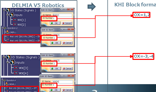
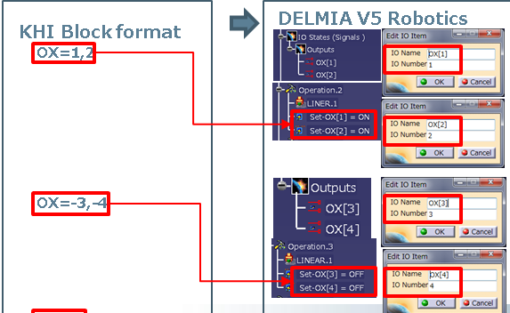
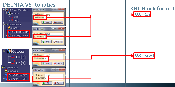
Block OX
The following is an example of a OX value for Kawasaki block format:
JOINT SPEED9 ACCU1 TIMER0 TOOL1 WORK0 CLAMP1 (ON,0,1,1) 2 (OFF,0,0,O) OX=1,2,-3,-4 WX= CL1=0.000,0.0,0.0,0.0,0.0,0.0,0.0 #[0,0,0,0,0,0,58.584]
The OX values will be uploaded into set signal commands. If the OXWXNegative device parameter is false (the default) then only positive OX values will be used.
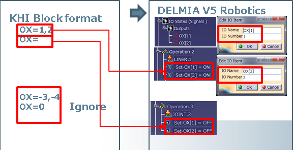
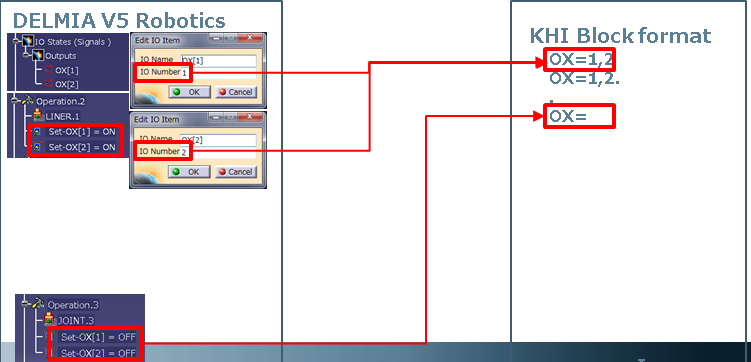
If the OXWXNegative parameter is true then both positive and negative values will be used.
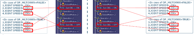
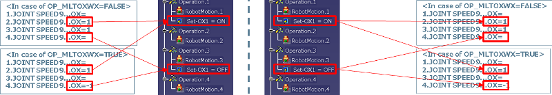
The parameter OX_PreOutput device parameter will also be used to control upload/download of OX signals. If the value is true (the default) then the set ON and set OFF activities will go to the previous robot motion.
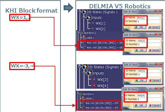
Block WX
The following is an example of a WX value for Kawasaki block format:
JOINT SPEED9 ACCU1 TIMER0 TOOL1 WORK0 CLAMP1 (ON,0,1,1) 2 (OFF,0,0,O) OX= WX=1,2,-3,-4 CL1=0.000,0.0,0.0,0.0,0.0,0.0,0.0 #[0,0,0,0,0,0,58.584]
The WX values will be uploaded in wait signal activities.