This command computes and loads the products, resources, and manufacturing assemblies that are assigned to processes that occur prior to the process that is currently loaded, based on the process sequence. This allows the current process be visualized within the manufacturing context.
-
Consider a project that has the following characteristics:
Task 1 processes both Sub Assy A-1 and Sub Assembly C. Task 2 processes Sub Assy A-2 and removes Sub Assembly C.
Task 3 has three operations which process Part A-3.a, Part A-3.b and Part A-3.c, respectively.
Process sequence
The computed manufacturing context is based on the process sequence defined for the project. Processes that occur before the loaded process in the sequence are considered when determining the manufacturing context, depending on the selected Manufacturing Hub Options.
The sequence for the project above looks like this:
-
Load a subprocess from the project (such as Op 3-b) in DPM:
-
When Op 3-b is loaded, all that can be seen in the PPR tree and 3D viewer are those products and resources associated to Op 3-b:
-
In many cases it would be advantageous to view the current process within the context of a manufacturing environment, where products from previous processes are also shown in the PPR tree and 3D viewer.
To load the products,
resources and manufacturing assemblies associated with processes prior to the loaded process, Load Manufacturing Context
 in the Manufacturing Hub toolbar.
 -
The Manufacturing Context dialog box is displayed:
-
Select Compute and Load Manufacturing Context check box and click
 .
.
The Manufacturing Context Inputs dialog box appears.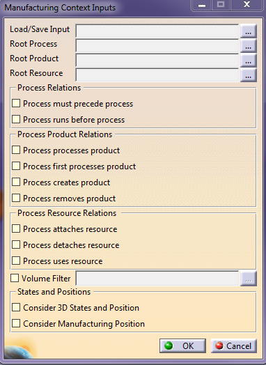
Specify the various inputs needed to compute the Manufacturing context on the fly.
The Reference Process used for the Manufacturing Context computation is the process loaded in V5. The filters used while loading the process in V5 client are used for the Manufacturing Context computation.
No context blob is saved against the reference process in the Manufacturing Hub database. -
Click
and browse the project structure in the database to select Root
Process, Root Product, and Root Resource in Manufacturing Hub - Select
dialog box.
It is mandatory to select Root Process, Root Product, and Root Resource. -
Select the relations to be considered for the Manufacturing Context computation.
-
Click
and specify the volume filter to be applied while computing the
Manufacturing Context.
The Specify Volume Filter Criteria dialog box appears. See
-
-
Select the “Consider 3D States and Position” option to specify they want the Manufacturing Context computation to obtain the position information from the Hub and the Manufacturing Context to be loaded in their 3D positions.
The 3D State to process condition to consider while loading the products/resources is determined by the order given below in decreasing order of priority:1. End Condition
2. 3D Context
3. Begin Condition
The following are the rules to determine which position to load the Manufacturing Context:
1. If an object is linked to a process which has the End condition defined for that object, then the product/resource will always be loaded in the position used for the End Condition.
2. If no End Condition is defined and the 3D Context Condition is defined, only then the product/resource will be loaded in the position used for the 3D Context Condition.
3. If neither the End Condition nor the 3D Context Condition is defined, only then the product/resource will be loaded in the position used for the Begin Condition.
4. If only a single condition is defined (Begin/End/3D Context), then the product/resource will be loaded in the position used for that condition.
5. If no 3D conditions are defined for the process, then the products/resources associated to these processes will be loaded in their design positions.
-
Save the selected inputs to an XML file on disk by clicking
.
Later on, you can choose to load the inputs from this saved XML file to populate the dialog rather than selecting them all manually.
You can also select input XML file created for computing the Manufacturing Context using the V5 context batch solver. When an input XML is loaded, the object inputs are checked and an error message is displayed, if they are not valid Manufacturing Hub database objects.
You have to manually update the required information in XML files saved from Manufacturing Context Inputs dialog box to used them as input in V5 context batch solver. -
Click OK to compute the Manufacturing Context and load the computed context in V5 client.
The position of each object is retrieved from the Manufacturing Hub and this will be the
-
Saving with Detailing
Once you compute and load a context and afterwards save a detailing
to the Manufacturing Hub, the loaded context structure is saved in
the detailing. Re-loading the detailing from the Manufacturing Hub
also reload the saved context tree. If a new context is computed and
loaded then the existing context structure is replaced with the new
one. If there occur some changes in loaded context then these
changes are saved only in detailing. There will be no change in
existing context blob stored in Manufacturing Hub against the loaded
process.
Loading of the Batch Computation
-
Load Context Representation
When enabled, it retrieves pre-created representation for the manufacturing context. This option will not load the product BOM list. -
Load Context Objects
When enabled, retrieve the existing manufacturing context from database and load the product list along with product representation.
Manufacturing Context Load Option
The options in the V5 Client-side Computation and Manufacturing Hub Server Computation sections are mutually exclusive. If you select any option in the Server Computation section, the options set in the Client Computation section get de-selected and vice versa. If the is no pre-computed Manufacturing context/context representation available, the options in the Manufacturing Hub Server Computation section will be disabled accordingly.
Incremental Loading of Contexts
Last Loaded Context Information
Save Currently Loaded Context InformationBoth load and save command will be combined into single command,
The changes named inputs through Manufacturing Context Inputs dialog,
user doesn’t save the modified inputs through Load/Save Inputs dialog
and Clicks on Ok in the Manufacturing Context inputs dialog then the
named inputs will not be overwritten and hence no Overwrite Inputs
warning displayed.
And also if you specify whether user wants to consider 'Volume Filter'
or not. A checkbox for 'Volume Filter' is provided in the Manufacturing
Context Inputs dialog for the same. If the user checks it, the
corresponding ‘…’ button will be enabled and he can specify the 'Volume
Filter'. If user unchecks it then the corresponding ‘…’ button will be
disabled and the volume filter condition (even-if it is already
specified) will not be considered for computing on-the-fly manufacturing
context. When user saves the inputs, the volume filter condition will be
saved to the XML blob only if the 'Volume Filter' checkbox is checked.
Limitations
- It will not be possible to save inputs in XML file on hard disk
and not possible to load inputs from XML file saved on hard disk
- The input xml generated by Batch solver cannot be used as Input
to the Manufacturing Context Inputs Dialog.
5 Client Computed
Manufacturing Context
![]()
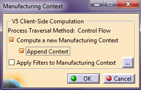
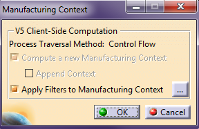 Compute a new Manufacturing Context
When enabled, a new Manufacturing Context will be computed.
By default, this check box is selected.
Defining and Applying Filters
User-defined filters based on product, resource and volumetric attributes may be applied to a Manufacturing Context.
-
After starting the Load Manufacturing Context command to display the Manufacturing Context dialog, click
to select the filters to
be applied:
Selecting the option Apply filters to Manufacturing Context will display the following error message, if the client-side context has not yet been computed or if this option is chosen by itself without selecting the first option.
-
The Specify filter(s) to apply dialog box is displayed:
This dialog lists defined Product Attribute Filters, Resource Attribute, and Volume Filters, and allows for filters to be added or edited, removed, loaded and saved.
Adding a New Process Attribute Filter
-
Click Process Attribute Filter to highlight it.
-
Click the Add/Edit button
 to display the
Specify Filter
Criteria dialog box:
to display the
Specify Filter
Criteria dialog box:
This dialog specifies four different areas of criteria, defined as follows:
Plantype
Allows for the creation of a criterion for a given plantype or for all the plantypes of the filter scope (all product or all resource plantypes). Note that the values of the other fields of this dialog box are lost when the Plantype field is modified.Attribute
Lists the available attributes (all attributes with the "Display in Finder" option set in the Process Engineer Configuration manager) for the selected object type.Operator
Lists the different operators based on the the Attribute type selected (==, != LIKE, NOT LIKE for string attribute, ==, !=, >, <, >=, <= for numerical attributes).Value
Displays the value(s) to use for filtering for this attribute. By default, only one value can be defined per attribute. However, if the operator used for the attribute is = or !=, then several values may be specified (combine with an OR operator for the = operator and by and AND operator for the != operator). Three buttons are available to manage the value(s):Add allows the user to enter a value for the attribute. When clicking on the button, a dialog box will be displayed to enter the value (with the value field empty when opening the dialog box):

Depending on the selected attribute, this field may be either a list box, date editor or text field.
Remove allows the user to remove a value from the list. This button is enabled only when an entry in the value list is selected.
Edit allows for an existing value to be edited. This button is enabled only when an entry in the value list is selected. When clicking on the button, a dialog box will be displayed to update the value selected in the list:

Adding a New Product or Resource Attribute Filter
-
Click Product Attribute Filter, or Resource Attribute Filter to highlight it.
-
Click the Add/Edit button
to display the
Specify Filter
Criteria dialog box:
This dialog specifies four different areas of criteria, defined as follows:
Plantype
Allows for the creation of a criterion for a given plantype or for all the plantypes of the filter scope (all product or all resource plantypes). Note that the values of the other fields of this dialog box are lost when the Plantype field is modified.Attribute
Lists the available attributes (all attributes with the "Display in Finder" option set in the Process Engineer Configuration manager) for the selected object type.Operator
Lists the different operators based on the the Attribute type selected (==, != LIKE, NOT LIKE for string attribute, ==, !=, >, <, >=, <= for numerical attributes).Value
Displays the value(s) to use for filtering for this attribute. By default, only one value can be defined per attribute. However, if the operator used for the attribute is = or !=, then several values may be specified (combine with an OR operator for the = operator and by and AND operator for the != operator). Three buttons are available to manage the value(s):Add allows the user to enter a value for the attribute. When clicking on the button, a dialog box will be displayed to enter the value (with the value field empty when opening the dialog box):
Depending on the selected attribute, this field may be either a list box, date editor or text field.
Remove allows the user to remove a value from the list. This button is enabled only when an entry in the value list is selected.
Edit allows for an existing value to be edited. This button is enabled only when an entry in the value list is selected. When clicking on the button, a dialog box will be displayed to update the value selected in the list:
Adding a New Volume Filter
-
Click Volume Filter to highlight to display the Specify Volume Filter Criteria dialog box
-
Select the values and click OK.
This dialog specifies four different areas of criteria, defined as follows:
Boundary Operator
May be set as Partly In, Partly Out, Full In or Fully Out.
When Fully In is selected, parts that are completely inside the bounding box are loaded. (Only Part1 will be loaded in the scenario above.)
When Fully Out is selected, parts that are completely outside the bounding box are loaded. (Only Part2 will be loaded in the scenario above.)
When Partly In is selected, parts that are either fully or partly inside the bounding box are loaded. (Parts 1, 3, 4 are loaded in the scenario above.)
When Partly Out is selected, parts that are either fully or partly outside the bounding box are loaded. (Parts 2, 3, 4 are loaded in the scenario above.)
Boundary Clearance
Specifies the clearance value. The clearance value enlarges or shrinks the bounding box in all directions, allowing for more or less data to be loaded in the computed manufacturing context.Reference Product
Specifies a product to be saved as a reference for the volume filter.When a reference product is used, any transformation in the position of the reference product is also applied to the volumetric filter bounding box. This maintains the focus on the volume of interest for filtering purposes, as the bounding box is shifted along with the product data.
Clicking the Reference Product button allows for the selection of a product in the PPR tree in the current document. After a selection is made, the instance name of the selected product is displayed in the corresponding text field. See Volume filter limitations below for restrictions on selecting reference product data.
Bounding Box Co-ordinates
Specifies the bounding box coordinates.If min and max values have been entered for the Bounding Box Coordinates, Draw Bounding Box can be used to draw a bounding box in the 3D viewer. This bounding box can be resized with the mouse pointer. When manipulated in this manner, the coordinates in the dialog are dynamically updated. The defined bounding box can also be edited by manually changing the coordinates in the dialog.
Once a Volume Filter is defined, another Volume Filter cannot be added, as only one volume is considered for filtering. For this reason, the Add/Edit button becomes disabled when the Volume Filter node is selected after a Volume Filter has already been defined.
Using the Backdrop Viewer
To aid in defining the bounding box accurately, select Activate Backdrop Viewer to display a 3D window that contains a semi-transparent image of the entire assembly.
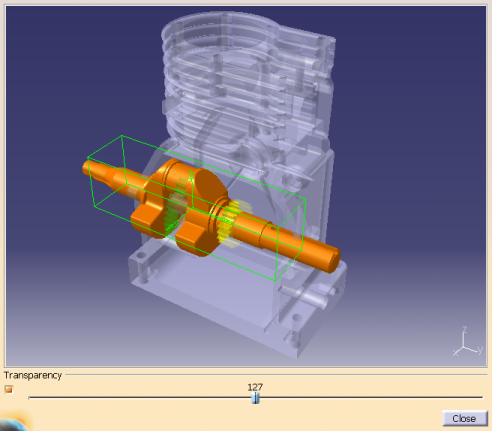 |
To display the backdrop image, a CGR representation of the end product must be specified for the 'graphicname' attribute of the product BOM node in the Manufacturing Hub project. This BOM node then must be selected as the BOM while loading data into DPM.
The corresponding CGR is displayed at the position specified on the BOM node with a default transparency of 50% as shown above.
|
If bounding box co-ordinates are already defined in the Specify Volume Filter Criteria dialog box, this bounding box is drawn in the 3D viewer when Draw Bounding Box is clicked. If no bounding box values are defined, selecting any of the product data in the 3D viewer will display its bounding box. Note that the back drop image itself is not selectable. The user can also select the product data from the main window to display a bounding box in the viewer. The bounding box in the viewer can be manipulated to accurately define a specific volume of interest.
After a satisfactory bounding box has been defined, click Close to dismiss the viewer.
Volume Filter Limitations
- This filter mechanism is not available to filter the manufacturing context when the Automatic computation of Manufacturing Context at load time option is enabled.
- Volumetric filtering is not available when loading a PPR project in DPM. It is available only to compute the manufacturing context after loading a project in DPM.
- The volume filter is applicable only for products and hence will filter only loaded products as part of the manufacturing context.
- The specification of a bounding box cannot be performed by selecting multiple parts. In addition, only one volumetric filter may be specified.
- Volumetric filtering is based on the bounding box information of a part. If a part is imported from ENOVIA, its bounding box information will also be imported and available in Process Engineer. However, if the part is newly created in Process Engineer, its bounding box information is not available and will not be filtered.
- The design position of a part is considered when applying a volumetric filter. Any 3D manufacturing positions defined in DPM are not considered for this purpose. In addition, when the bounding box is specified in DPM, only those parts whose design positions fall within the specified volume (as defined by the 3D Bounding Box) are loaded from Process Engineer.
- If the position of the reference product is modified in V5 and subsequently saved back to ENOVIA, the product data must be imported from ENOVIA (incremental import) into the Manufacturing Hub again to update its position information. If the product data is not re-imported, the volumetric filter defined with respect to this reference product will not have its bounding box updated accordingly and the filtering results will not be accurate.
- When saving filters against a process:
- Only one volume filter criteria can be saved against the process.
- The name of the volume filter must be unique.
- The filter saved against a process can be modified only if that process is currently loaded in DPM and the process is in an In-Work state.
- Resource data cannot be selected as a reference product
- A reference product may only be selected from product data loaded when the project the project was loaded.
Removing a Filter
The Remove button
![]() is used to remove a criterion
or to empty a filter.
is used to remove a criterion
or to empty a filter.
To remove a criterion, select a criterion on the list and then click on the Remove button.
To empty a filter, select one of the two filter nodes (Product Attribute Filter or Resource Attribute Filter) and then click on the Remove button. This button is only enabled when a criterion/filter is selected.
Saving a Filter
The Save button
![]() is used to save a filter for
reuse. Filters are saved in the database and available for any user from any machine via the Load button (described
below), and are assigned to the master Plantypeset of the current project.
is used to save a filter for
reuse. Filters are saved in the database and available for any user from any machine via the Load button (described
below), and are assigned to the master Plantypeset of the current project.
When the Save Filters dialog is displayed, use the checkboxes to select a filter type to save and enter the name of the filter(s) to save in the Name field:
 |
Volume filters may be saved against multiple processes. If a filter that has been saved against multiple processes is modified, the system will not allow it to be overwritten. It must be saved as a new filter with a different name.
Loading a Saved Filter
You can store previously stored filter.
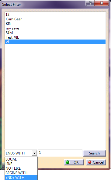
To search a particular filter, select operator and click EQUAL, LIKE, NOT LIKE, BEGINS WITH, ENDS WITH from the list and enter a value, click Search. The value is selected. During search, if only one matching filter is found, then that filter is highlighted in list of filters. If there are multiple number of search results, then an additional dialog (search result) is displayed to select one filter. Click OK, the selected filter will be highlighted in list of filters.
The Load filter button
![]() and select
a filter and click OK to load it.
and select
a filter and click OK to load it.
|
Click Search, the Select Filter dialog box appears.
|
If
there are no filters matching the search criteria, then the message is
displayed: No filter meets the specified search criteria
Specify the search string before you click Search. If you do not provide
the error message: Please specify a valid search string is displayed.
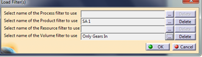
Once a filter is selected in the ‘Select Filter’ dialog, click OK to
select the filter to load or delete. Selected filter name is displayed
in the editor in the ‘Load Filter(s)’ dialog.
Note: The dialog is applicable for all types of filter (process,
product, resource and volume).
If there are no filters of that particular type saved in Manufacturing
Hub DB, then upon clicking the ‘…’ button in the ‘Load Filter(s)’
dialog, the following message will be displayed
Click OK, the Load Filter(s) dialog box is updated with the selected
volume filter.
Limitations:
-
The filter search functionality is case sensitive and a proper search string should be input considering this
-
All commands where you have to select previously saved volume or attribute filter will have same behavior.
- Delete buttons are available in this dialog box to delete a selected filter.
Appending in the Client side Context
You can load one or more manufacturing context in V5 DPM optionally using the existing load commands one after the other incrementally. And also, allows you to append newly computed manufacturing context to an already loaded context.
Append
Context’ option will be enabled and available for selection only if you
have chosen the option ‘Compute a new Manufacturing Context’.
If the option is not selected, then the ‘Append Context’ option will be
unavailable and cannot be selected.
The ‘Append Context’ option is enabled and available for selection only if the user has chosen the option ‘Compute a new Manufacturing Context’.
You can compute and load a new context using ‘Append context’ option, new context will be merged with the existing context. If some of the products, which are already loaded in V5 session (either as authoring product or the part of previously loaded manufacturing context) and if they are also present in newly computed context, then the products will not be loaded again.
You can change visual parameters (color, transparency) using ‘Edit Visual Parameters of Manufacturing Context’ and this is applicable for combined context, it will not be possible to set different parameters for each context.
After loading the multiple contexts, if you compute and load a new context without selecting the ‘Append Context’ option, then a warning message: All context loaded previously will be removed and new context will be loaded. Do you want to continue? if you select ‘Yes’, all the previously loaded contexts will be removed and the new context will be added. If you select No, then command will be canceled.
Save with Detailing
After loading context when user saves a detailing to the Hub, loaded context (merged) will be saved only in the detailing. No change in save behavior.
Limitations:
-
You can change visual parameters (color, transparency) using ‘Edit Visual Parameters of Manufacturing Context’ command and this is applicable for combined context, it is not possible to set different parameters for each context.
Notes
-
The Load Manufacturing Context command considers the following relations when computing the manufacturing context:
- Process processes product
- Process 1st processes product
- Process creates product
- Process removes product
- Process attaches resource
- Process detaches resource
- The manufacturing context can also be loaded automatically when the process is loaded from the Manufacturing
Hub by enabling the Automatically compute Manufacturing Context at load time
option on the ‘Advanced Options’ of the Manufacturing Hub
tab page in ‘Digital Process Manufacturing’ V5
Tools options. Any attribute and volume filters last used during
the computation of Manufacturing Context will not be considered
when loading the context using this auto load option.
-
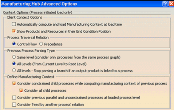
Other options available on the Manufacturing Hub Options page determine how the previous processes are parsed, including whether:
- products are loaded only from processes that are at the same level of the current process, or from all levels
- child processes are considered
- "feed by another process" relations are considered
- unconstrained previous processes' products and resources are considered
-
If there are no filters matching the search criteria, the message No filter meets the specified criteria appears, Click OK
-
If there is no search criteria, then the an error message Please specify a valid string appears.
-
If there are no filters saved and if you click search, the message No filters saved in database! appears.