The support represents the direction in which the points are translated: along a line or in a plane. The manipulators are automatically displayed according to this direction:
 Normal to compass: control points are translated along the compass
normal direction. Take care that the compass position can be redefined at
any time. The compass normal is the w compass direction.
 Mesh Lines: control points are translated along the directions
defined by the mesh lines. A mesh line direction is defined by the vector
between two consecutive control points.
 Local Normals: control points are translated along the normal to
the surface computed at each control points.
 Compass
Plane: control points are moved in the compass plane. Take care
that the compass position can be redefined at any time. The compass plane
is the plane represented by the x|u and y|v compass axes.
 Local Tangents: control points are moved in the tangent plane to
the surface computed at each control points.
This option is P2-only. Screen Plane: control points are moved in to the plane defined by
the computer screen.
This option is P2-only.
-
Click the Control Points icon:

The Control Points dialog box appears. 
-
Move the Compass onto Surface.1.
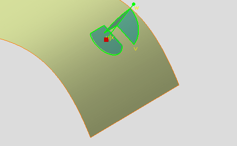
-
Select Surface.1.
-
Click the Points only icon if not already selected:

Normal to Compass Support
-
Click the Normal to compass icon:


The control point manipulator displays the direction line along which the control point will be translated. 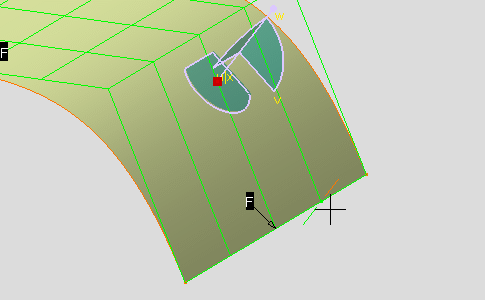
-
Select the control point and drag it.
After translating the control point along the compass normal direction, the surface looks like this: 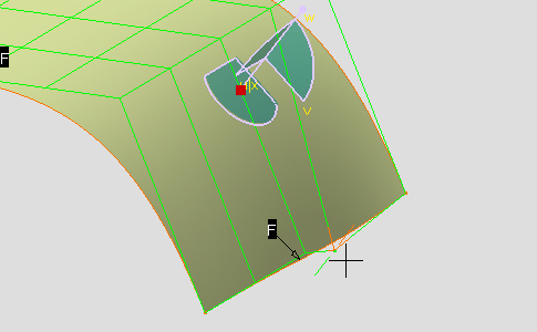
-
Click OK to validate the modifications and close the dialog box.
Mesh Lines Support
-

- You have to select the mesh line to select the control point.
- According to the mesh line selection location, the closest control point to this location will be selected.
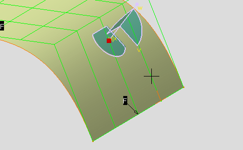
-
Select the mesh line close to the control point to be moved and drag it.
After translating the control point along the mesh lines directions, the surface looks like this: 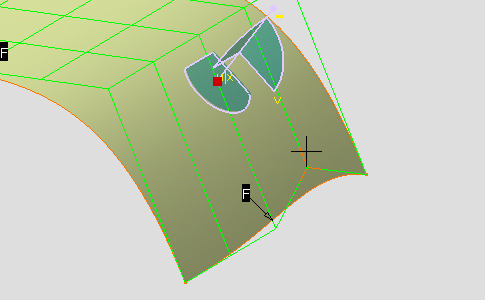
-
Click OK to validate the modifications and close the dialog box.
Local Normals Support
-

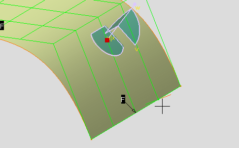
- The control point manipulator displays the normal direction line along it the control point will be translated.
- If you select several control points, they will be translated along their own mesh direction.
- After you release the mouse button, the normal direction is recomputed.
-
Select the control point and drag it.
After translating the control point along the local normal directions, the surface looks like this: 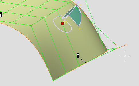
-
Click OK to validate the modifications and close the dialog box.
Compass Plane Support
-

-
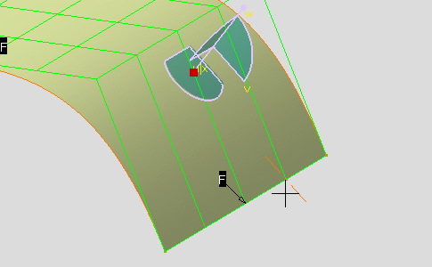
The control point manipulator displays
direction lines along it the control point will be moved:
- If you select the center of the control point manipulator, the control point will moved in a parallel plane to the compass plane.
- If you select one of the two directions of the control point manipulator, the control point will translated along it.
-
The control point manipulator displays
direction lines along it the control point will be moved:
-
Select a control point manipulator direction and drag it.
After moving the control point in the compass plane, the surface looks like this: 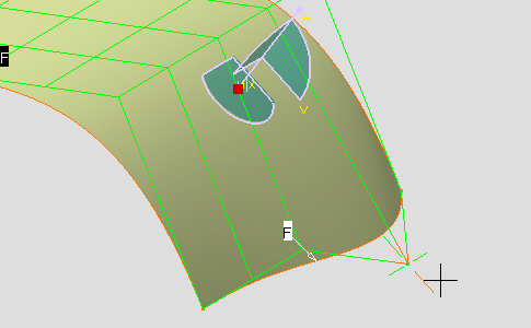
-
Click OK to validate the modifications and close the dialog box.
 Local Tangents Support
-
Click the Local Tangents icon from the Support frame:


- Approaching the cursor close to a control point selects it.
- The control point manipulator displays the tangent direction line along it the control point will be translated.
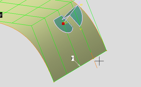
-
Select the control point and drag it.
After moving the control point in the tangent plane, the surface looks like this: 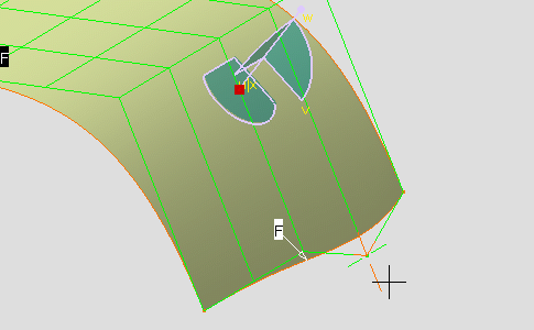
-
Click OK to validate the modifications and close the dialog box.
 Screen Plane Support
-
Click the Screen Plane icon from the Support frame:


- Approaching the cursor close to a control point selects it.
-
The control point manipulator displays
direction lines along it the control point will be moved:
- If you select the center of the control point manipulator, the control point will moved in a parallel plane to the compass plane.
- If you select one of the two directions of the control point manipulator, the control point will translated along it.
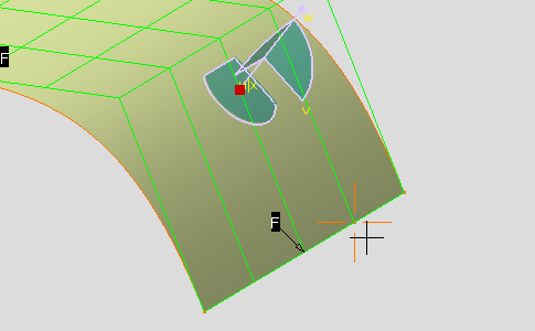
-
Select a control point manipulator direction and drag it.
After moving the control point in the computer screen plane, the surface looks like this: 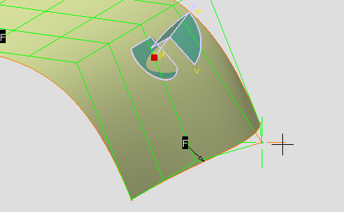
-
Click OK to validate the modifications and close the dialog box.