- Manipulation filters
 Points only:
allows you to select control points selecting points only.
Points only:
allows you to select control points selecting points only. Mesh only:
allows you to select control points selecting their mesh lines only.
Mesh only:
allows you to select control points selecting their mesh lines only. Points and
mesh: allows you to select control points either selecting points
or their mesh lines.
Points and
mesh: allows you to select control points either selecting points
or their mesh lines.

If the Filter options : deselect all points option is selected in Tools > Options > Shape > FreeStyle > General tab, Selection options area, all the selected control points of the selected elements are automatically deselected when the Filters mode is changed. -
 Select all points: selects all the points of the
control points mesh. This command is also available from the mesh lines
and control points contextual menu.
Select all points: selects all the points of the
control points mesh. This command is also available from the mesh lines
and control points contextual menu. -
 Deselect all points: deselects all the
points of the control points mesh.
Deselect all points: deselects all the
points of the control points mesh.  Display Inflections: displays arrows at the
control points representing their normal vectors and deduces the
inflection at the control point locations. These arrows are displayed
when the surface is not locally planar at the considered control points
and when the control points are connected to three mesh lines at least.
Display Inflections: displays arrows at the
control points representing their normal vectors and deduces the
inflection at the control point locations. These arrows are displayed
when the surface is not locally planar at the considered control points
and when the control points are connected to three mesh lines at least.
This option is P2-only.-
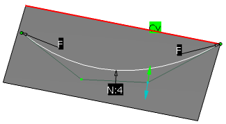
 Display deviation: displays the maximal deviation
location and value in 3D, the deviation value is also displayed at the
bottom of the dialog box.
Display deviation: displays the maximal deviation
location and value in 3D, the deviation value is also displayed at the
bottom of the dialog box. -
 Display Harmonization Planes: allows you to display the planes
computed according to the harmonization law. This option is only
available in the Mean plane and 3-Points plane
options of Harmonization.
Display Harmonization Planes: allows you to display the planes
computed according to the harmonization law. This option is only
available in the Mean plane and 3-Points plane
options of Harmonization. -
 Global Mesh Mode: allows you to modify all the selected meshes at
the same time, in case of multi selection. When this option is
activated, rows of control points are propagated to the neighboring mesh
if a contact is found between them.
Global Mesh Mode: allows you to modify all the selected meshes at
the same time, in case of multi selection. When this option is
activated, rows of control points are propagated to the neighboring mesh
if a contact is found between them.This option is available if the Mesh only mode is selected and the continuity at the common endpoint or the common edge is Free(F).
When approaching the control points mesh, the cursor changes from the arrow representation to a cross representation and the nearest mesh line or control point is automatically pre-selected. The cursor representation can be customized from the Tools Options settings.
Shift and Ctrl keys allow you to add mesh lines or control points to the selection.
-
Click the Control Points icon:

The Control Points dialog box appears. 
-
Select Surface.1
Control points and the mesh are displayed on the surface. -
Click the Elements List icon:

The Elements dialog box appears and displays the list of selected elements. 
-
Click Close in the Elements dialog box.
-
Click the Normal to compass icon if not already selected:

-
Click the Points only icon if not already selected:
Approaching the cursor close to the mesh allows you to select control points only. 
-
Click the point or click close to it to select it.

To select multiple control points in the 3D area:
- Hold down Ctrl and select the control points.
- You can select multiple control points using the selection trap. When the selection trap starts over the geometry:
- Click
Selection Trap above Geometry
 in the
Select toolbar.
in the
Select toolbar. - Drag the trap until the control points you want to select are completely inside the bounding outline.
- Release the pointer.
-
Click the Mesh only icon from the Options frame:
Approaching the cursor close to the mesh allows you to select mesh lines only. 
-
Click the mesh line or click close to it to select itself and its control points.

-
Click the Points and mesh icon from the Options area:
-
Select both Surface.1 and Surface.2.
Control points and the mesh are displayed on both surfaces. 
-
Click the Manipulators Snap icon from the Dashboard toolbar:

-
Select the first control point.
Note that mesh representations have been simplified. 
-
Select the second control point.

The first control point has been snapped onto the second control point. 
-
Click OK to validate modifications and close the dialog box.
Selection and Manipulation States
- Selection state: You can only select some geometries to be manipulated, but cannot manipulate them. The mesh will be displayed on those latter, but cannot be picked.
- Manipulation State: In the second one, the selected elements can be manipulated. No geometry can be selected. Click in the empty space should not de-selected the selected geometries.
New Selection of Elements
- When you click on the element to be manipulated (with no modifier key), the command automatically jumps to the manipulation state, in order to enable the manipulation of the element.
- When the you click on the element to be manipulated with CTRL pressed, the command remains in the selection state, so that multi-selection is allowed.
- When the you click in the empty space to de-select all the geometries, the command remains in the selection state, as no selection is done.
- When the you click on the bag icon near the selector and opens the multi-selection dialog, geometries can be selected and/or de-selected with or without CTRL key pressed. As soon as you close the multi-selection dialog, the command automatically jumps to the manipulation state.
- F8 shortcut can be used to quickly switch from one state to the other (unless the multi-selection dialog is opened).
New Selection Trap of Control Points
The settings for the Mesh are mentioned under the topic Manipulators > New Setting for the Mesh.
Edge Selection and Manipulation
When a topological issue is detected, a dialog box pops up with a warning. This was not the case in V5R14.