Open the FreeStyle_Part_50.CATPart document.
-
Click Dress-Up
 in the Generic Tools
toolbar.
The Curves and surfaces dress-up dialog box is displayed.
-
Select the elements you want to dress in the Objects box.
In the Objects box, selected elements can be of two types: - Individual elements, for instance: curve, surface, or face.
- Set of elements, for instance: Geometrical Set, Ordered Geometrical Set, or PartBody.
You can select one or several elements by doing one of the following:
- To select a single element, click the element in either the work area or the tree.
- To select multiple elements:
- Click
 next to
the Objects box to display the
Objects list dialog box.
 - Select the required object.
- If necessary, remove or replace objects in the Objects list dialog box.
- Click Close.
OR
- Hold down Ctrl and select the required elements.
- Press F8.
Dress-Up applied to sets of elements (or to individual elements, respectively) enables to associate a Dress-Up's representation for each element of the sets (respectively for each individual element).
Once applied to sets of elements (or to individual elements, respectively), Dress-Up's representations are automatically updated according to the changes (shape modification, moving, deletion or addition of elements) occurring within the sets (or onto the individual elements, respectively). The element name or the number of selected elements is displayed in the Objects box.
You can select the Geometric Set or valid elements (surfaces
and curves) under it as input elements. Press Ctrl key for multiple selection of
geometric sets.The
![]() icon
lets you edit the list of surfaces selected for analysis. Click the icon
to display the Objects List dialog box that allows you to
remove or replace the selected elements.
icon
lets you edit the list of surfaces selected for analysis. Click the icon
to display the Objects List dialog box that allows you to
remove or replace the selected elements.
- Control Points: Select this
check box to display the control points on
the selected curves with the settings as
defined in the dialog box. By default this
option is deactivated.
- You can define the color of the control points mesh.
- You can define the line type of the control points.
- You can define the control point style.
- Segmentation: Select this
check box to display the segmentation on the
selected curves with the settings as defined
in the dialog box. By default this option is
deactivated.
- You can define the color of the segmentation points.
- You can define the segmentation point style.
- Control Points: Select this check box
to display the control points on the
selected surfaces with the settings as
defined in the dialog box. By default this
option is deactivated.
This option functions exactly identical to the Control Points option in the Curve area. - Display control points on edges:
Select this check box to display the control
points only on the edges of the selected
surfaces. By default this option is
deactivated.

When control points on the surface are not displayed, this option allows you to display the control points on the limit edges of the surface only. - Segmentation: Select this check
box to display the segmentation on the
selected surfaces with the settings as
defined in the dialog box. By default this
option is deactivated.
This option functions exactly identical to the Segmentation option in the Curve area.- You can define the line type of the segmentation.
- Iso-curves: Select this check box
to display the number of U and V
isoparametric curves on the selected
surfaces with the settings as defined in the
dialog box. By default this option is
deactivated.
- You can define the color of the isoparametric curves.
- You can define the isoparametric curve style.
- You can define the number of U
and V isoparametric curves from the
NbU and NbV
drop-down lists. The number can be
any number from the list or Order.
Order displays the isoparametric
curves in U and V corresponding to the
internal mathematical order of the
surface.
For example, if the order of the surface is 5 in U and 3 in V, you can see that 5 iso-curves in U direction and 3 in V direction are displayed.
- Control Points: Select this
check box to display the control points on
the selected faces with the settings as
defined in the dialog box. By default this
option is deactivated.
This option functions exactly identical to the Control Points option in the Surface area. - Segmentation: Select this
check box to display the segmentation on the
selected surfaces with the settings as
defined in the dialog box. By default this
option is deactivated.
This option functions exactly identical to the Segmentation option in the Surface area. - Iso-curves: Select this check
box to display the number of U and V
isoparametric curves on the selected
surfaces with the settings as defined in the
dialog box. By default this option is
deactivated.
This option functions exactly identical to the Iso-curves option in the Surface area.
-
Remove Dress Up
 : Select the elements
and click icon to remove all the dress-up elements
from selected elements at one time. If you click the
icon, a message is displayed proposing you to remove the dress up
applied to the children of the object.
- Click Yes to remove the dress up applied to the children in addition to the selected object.
- Click No to remove the dress up to the selected object.
- Click Cancel to cancel remove dress up.
- Apply immediately
 :
Click this icon to apply the display changes immediately to the
selected elements without clicking Apply.
 - Global mode
 : Click
this icon to apply dress-up to all the elements in the part according to
the set parameters.
-
Rendering styles – Select the required option to define the rendering style.
For more
information, see the CATIA Infrastructure: Using Rendering styles. -
Visibility modes for the points, wires, and axes –
By default, the Default Points Visibility Mode
 , Default Wires
Visibility Mode
 , and Default Axes or Planes Visibility Mode
 are
selected.
The visibility options for the points, wires, and axes are set as per the settings of the No points, No wires, and No axes check boxes in the View Mode Customization dialog box, respectively.
For more information, see the CATIA Infrastructure: Customizing the View Mode.
Notes:- Click Hide Points
 , Hide Wires
 , and Hide Axes or
Planes
 to hide the point, wire, and axis entities,
respectively.
 - Click Show Points
 , Show Wires
 , and Show Axes
or Planes
 to show the point, wire, and axis
entities, respectively.
 - If you first define or modify the visibility options for points, wires, and axes in the View mode Customization dialog box and then create a variant, the visibility options will be in the default mode in the Curves and surfaces dress-up dialog box.
Click Hide Points
 , Hide Wires
 , and Hide Axes or Planes
 to
hide the point, wire, and axis entities, respectively.
- Click Hide Points
-
Select the curve.
-
In the Curve area, select the Control Points and Segmentation options. You can change the color, linetype and style also.
-
Click Apply.
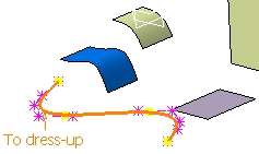
-
Select the Apply immediately check box.
-
There are three states of the options available in the Curves and surfaces dress-up dialog box:
- Not selected: When the selected elements do not have any dress-up feature defined, the options in the Curves and surfaces dress-up dialog box are not selected.
- Selected: When the selected elements have the same parameters (color, linetype, symbol and selection of the option) for the defined dress-up feature, such options are selected in the Curves and surfaces dress-up dialog box.
- Undefined: When the selected elements
have the different parameters (color,
linetype, symbol and selection of the
option) for the defined dress-up feature,
such options are in undefined state in the Curves and surfaces dress-up
dialog box.

-
The option will remain in undefined state till you change it.
-
You can press F8 key to change the selection state. After selecting elements, press F8 and modify the parameters you want to. In this state your existing selection will not be deselected even if you click anywhere in the 3D area. Press F8 again to go back to the selection state.
-
The Dress-Up command can be launched when another command (Styling Extrapolate, Extend, etc.) is running. The other command is temporarily deactivated and you can apply the dress-up features to elements. After you click OK in the Dress-Up command, the previous command is reactivated.
-
If dress-up is applied to an element, while editing the control points of this element, the dress-up representation of the control points and control points on edges of this element is hidden.
-
Select a surface.
-
In the Surface area, select the Control Points and Segmentation options. You can change the color, linetype and style also. You can see that the display options are applied immediately on the selected surface.
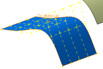
-
Clear the Control Points check box.
-
Select the Display control points on edges and Iso-curves options.
-
In the NbU and NbV list, select the number of isoparametric curves. In this case select Order.
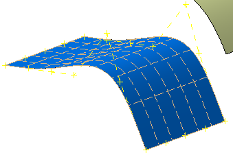
-
Select a face.
-
In the Face area, select the Control Points, Segmentation and Iso-curves options. You can change the color, linetype and style also.
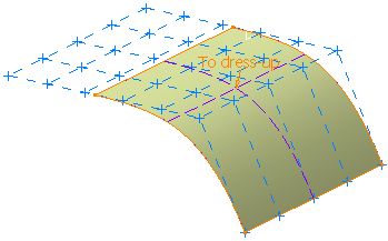
The control points displayed are of the underlying surface of the face.
-
Click OK. You can see that the dress-up elements are displayed as selected in the Curves and surfaces dress-up dialog box.
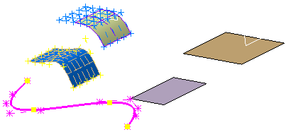
-
Click Dress-Up again.
-
Select the elements from which you want to remove the dress-up features. In this case select all the elements.
-
Click Remove DressUp
 .
.
-
To create a user-defined set of display options:
-
In the Display area of the dialog box, select the check boxes, colors and types you require for Curves, Surfaces and Faces.
-
Display Control points on edges: displays the control points only on the edges of the selected surfaces. When
control points on the surface are not displayed, this option allows you to display the control points on the limit
edges of the surface only.
-
-
Iso-curves:
-
NbU: defines the number of U isoparametric curves. The number can be any number from the list, none or the U surface order.
-
NbV: defines the number of V isoparametric curves. The number can be any number from the list, none or the V surface order.
-
-
In the Variants area, enter a name for your set of options.
-
-
Click New variant in the Variants area.
The new user-defined set of display options is added to the list of names in the Variants area. You can now use this variant as explained in the previous steps. -
To edit a user-defined set of display options:
-
In the Variants area, select the name of the set you want to edit.
-
In the Display area of the dialog box, select the check boxes, colors and types you require for Curves, Surfaces and Faces.
-
Click Save variant.
The document is saved.
-
-
To delete a user-defined set of display options:
-
In the Variants area, select the name of the set you want to delete.
-
Click Delete variant.
The set is deleted and is removed from the list of names in the Variants area.
-
-
Optional: Click Global Mode
 and select the parameters in the Display
area.
All the elements in the part are dressed up according to the set parameters.
Notes:- If you insert any visible element in the part, it will be automatically dressed up as per the global dress-up parameters.
- If you click Global Mode again, the visualizations of the previous local dress-up (before activation of the global dress-up mode) are recovered. In this case, all the elements inserted in the part after activation of the global dress-up mode remain undressed.
-
Optional: Click Remove DressUp
 .
.
-
Click OK.