Only geometry of topological cells is analyzed, therefore elements such as cloud of points, for example, are not analyzed.
Open the FreeStyle_15.CATPart document, or any .CATPart document containing geometrical elements.
-
Click Geometric Information
 .
.
-
Select the element for which you want to display information either in the geometric area or in the specification tree.
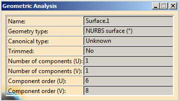
The Geometric Analysis dialog box is displayed.
Following information is displayed in the dialog box, such as:
-
the geometry type (NURBS surface or curve, Parameterized line, Plane, etc)
-
the canonical type
-
whether the element has been trimmed, or not
-
the number of components in both U & V direction (where applicable)
-
the component order in both U & V direction (where applicable).
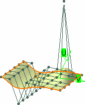
Moreover, a vector representing the element's orientation (U for a curve, and U & V for a surface) is displayed on the geometrical element itself.

-
In the case of a 3D curve created using the Control Points type, the maximum order is 6.
-
For sweep features the displayed geometry type will be the one of the included surface (e.g. NURBS surface).
-
For elements whose type is NURBS curve, Parameterized NURBS curve or NURBS surface, a (*) will be appended to the displayed type when the element is not rational, i.e., a polynomial one.
-
You can stack this command on top of the current command, i.e. that you editing an element using its control points, you can activate the Geometric Information icon. The current command is frozen, and when you exit the information command, you are back into the initial command.
-
You cannot select an element from the specification tree as the selected element might be too complex (i.e. be composed of more than one cell) and the system cannot determine which element is to be analyzed.
-
To display information on another element, select the element in the 3D area or in the specification tree.
The information in the dialog box is updated. -
Click Geometric Information
 to exit the command.

The geometry type is categorized as follows:
| Displayed Type | What is it ? | |
| Unknown geometrical element | Unknown geometrical element | |
| Geometrical element | Geometrical element | |
| Curve | Curve | |
| Conic section | Conic section | |
| Circle | Circle | |
| Ellipse | Ellipse | |
| Line | Line | |
| NURBS curve | Non Uniform Rational B-Spline curve | |
| Spline | Spline | |
| Foreign curve | Curve created by a CAA application | |
| Helix | Helix | |
| Edge curve | Curve group corresponding to a topological edge | |
| Parameterized curve | Curve defined in the parametric space of a surface | |
| Parameterized circle | Circle defined in the parametric space of a surface | |
| Parameterized ellipse | Ellipse defined in the parametric space of a surface | |
| Parameterized parabola | Parabola defined in the parametric space of a surface | |
| Parameterized hyperbola | Hyperbola defined in the parametric space of a surface | |
| Parameterized line | Line defined in the parametric space of a surface | |
| Parameterized NURBS curve | Non Uniform Rational B-Spline curve defined in the parametric space of a surface | |
| Parameterized spline | Spline defined in the parametric space of a surface | |
| Parameterized foreign curve | Curve created by a CAA application defined in the parametric space of a surface | |
| Cartesian point | Cartesian point | |
| Point on curve | Point lying on a curve | |
| Point on edge curve | Point lying on an edge curve | |
| Point on surface | Point lying on a surface | |
| Macro point | Point group corresponding to a topological vertex | |
| Surface | Surface | |
| Cylinder | Cylinder | |
| Sphere | Sphere | |
| Cone | Cone | |
| Torus | Torus | |
| Plane | Plane | |
| NURBS surface | Non Uniform Rational B-Spline surface | |
| Foreign surface | Surface created by a CAA application | |
| Offset surface | Surface generated by offsetting a reference surface | |
| Revolution surface | Surface of revolution | |
| Tabulated cylinder | Surface generated by translating a profile curve |
