This task shows you how to:
Create a Patch from Two or Three Points on a Plane
-
Click Unified Patch in the Surface Creation toolbar (Patches sub-toolbar).
-
Click 2-Point Patch
 or 3-Point Patch
 .
. -
Select Reference Support: Robot Plane.
The reference support can be:
Note: When you create a 2-point or 3-point patch, the Reference Support option is always selected and cannot be cleared.- The Robot Plane.
- A user-defined plane: Right-click to define the plane. The patch is created on a plane parallel to the reference support plane.
- A surface: Select the element in the work area. According to the Projection Type, the patch is created on a plane parallel to the mean plane of the reference support or is projected and fitted to the reference support.
- Select Projection Type: Planar Direction.
Option Description Planar Direction Creates the patch on a plane passing through the first selected point. The result is a planar patch. Project on Plane Creates the patch on the reference support plane. The result is a planar patch.
Note: This option is only available if the reference support is a plane.Project on Mean Plane Creates the patch on the mean plane of the reference support. The result is a planar patch.
Note: This option is only available if the reference support is a surface.Project and Fit to Support Fits the patch to the reference support. The patch is not necessarily planar.
Note: This option is only available if reference support is a surface.
- Click in the work area to position the starting
point.
- Points selected in a free space directly lie on the specified plane.
- Points selected on existing geometry are projected onto the plane.

To create a 2-point patch with the starting point at its center, press Ctrl and select the position. - To create a 3-point patch, do the following:
- Move the cursor to a different position. A line appears showing the direction of the axis of the patch.
- Click again.
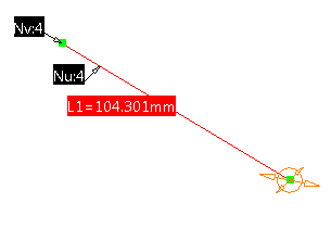
- Move the cursor to form the patch.
An outline is previewed and two values are displayed indicating the length and the width of the patch.
The patch is created in a plane parallel to the Robot plane and passing through the first selected point.
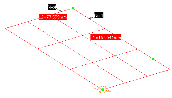
- Optional: Edit the patch orders by
the Nu:
and Nv:
order tags displayed at the geometry or right-click
the order tag and select Edit Orders
at any time during the creation.
- Right-click the labels to activate the Order context menu and select Link Orders to have identical orders in U and V direction.
- Right-click in the work area at any time during the creation, as long as the selection is not finished and select Edit Orders in the context menu.
- Complete the patch creation by doing one of the
following:
- Click again to define the opposite corner of the patch.
- Right-click the dimension tag and select Edit Dimensions, enter the required values, and click OK.
- Optional: Refine the patch by moving
the handles or by editing orders and dimensions.

In case of a 3-point patch or 4-point patch, the handles are by default moved in the U and V direction of the patch. With the Use Reference Support Direction option in the handle's context menu, they can be moved in the direction of the reference support. - Click OK.
A planar patch is created.
Create a Patch from Four Points Fitted to a Support
-
Click Unified Patch in the Surface Creation toolbar (Patches sub-toolbar).
-
Click 4-Point Patch
 .
. -
Select the Reference Support check box, click into the box, and select a surface.
The Project and Fit to Support option is automatically selected and the result is a non-planar patch.
Notes:- If you select Planar Direction, Project on Plane, or Project on Mean Plane, the result is a planar patch.
- If the Reference Support check box is cleared, you can create both a planar or a non-planar patch depending upon the selection of points. The first three points must be selected on existing geometry.
-
Select any point in a free space or on existing
geometry.
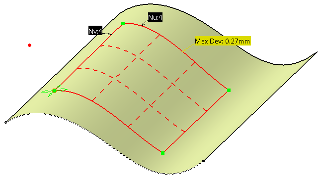
The projection of the selected point to the nearest point on the reference support is visualized in the work area. -
Successively, select three other points.
The resulting patch will not necessarily be planar. The maximum deviation of the resulting patch from the reference support is displayed at its location.
- Optional: To refine the patch, move the handles or edit the orders and dimensions.
-
Optional: Select a plane as the
Reference Support, and select four
points in a free space or on existing geometry.
The result is a planar patch. - Click OK.