This dialog box contains controls for:
|
General |
|
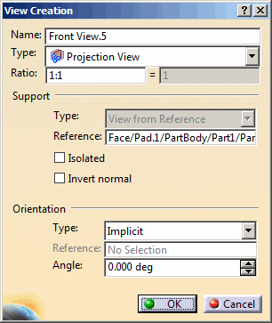
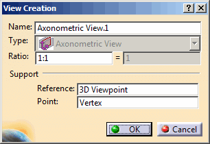
- Name
Defines the annotation view name. - Type
Defines the annotation view type.
The options in the Type combo box are as follows:
By default, Projection View is selected
- Ratio: Defines the annotation view ratio.
Support |
|
- Type
Indicates that the “View From Reference” is selected in the Views/Annotation Planes toolbar. - Reference
Displays the view reference geometry. - Isolated
Isolates the view from the geometry. In this case, you will then be able to modify the geometry or the axis system without changing the view definition.
By default, the view is associated with a planar face or an axis system.
Irrelevant in axonometric view context. - Point
Displays the point as point of view.
Relevant in axonometric view context only. - Invert normal
Inverts the view orientation. When the view annotation plane is moved on an axis system, the Invert normal option is not available because the view annotation plane takes by default the axis system orientation.
Irrelevant in axonometric view context.
Orientation |
|
|
|
|
- Type
Defines the annotation view horizontal axis orientation.
The options in the Type combo box are as follows:- Implicit: Lets the application choose the orientation of the horizontal axis.
- X Axis: Orientates the horizontal axis according to the X axis representation when possible.
- Y Axis: Orientates the horizontal axis according to the Y axis representation when possible.
- Z Axis: Orientates the horizontal axis according to the Z axis representation when possible.
- Parallel to line: Orientates the horizontal axis according to a selected line when possible.
- Normal to surface: Orientates the vertical axis according to the normal to a selected plane when possible.
- Reference
Displays the horizontal axis reference geometry.
Available only with Parallel to line and Normal to surface orientation types. - Angle
Defines the horizontal axis angle with reference geometry.