See Using a View/Annotation Plane for more information.
Open the
Common_Tolerancing_Annotations_01.CATPart document.
Select Change primary view plane and Resize view box
according to 3D model options in Tools > Options > Mechanical
Design > Functional Tolerancing Annotation > View/Annotation Plane
tab.
For more information, see Primary View settings.
-
Click Principal Views
 in
the
Views/Annotation
Planes toolbar.
The Principal View dialog box appears, the primary view is Front view.
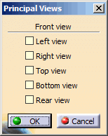

To change the primary view, click the robot arrows.
Depending on which arrow you clicked, the following permutations are applied:
- Right arrow: FRONT > LEFT > REAR > RIGHT > FRONT.
- Left arrow: FRONT > RIGHT > REAR > LEFT > FRONT.
- Up arrow: FRONT > BOTTOM > REAR > TOP > FRONT.
- Down arrow: FRONT > TOP > REAR > BOTTOM > FRONT.
The view bounding box is displayed in the 3D area.
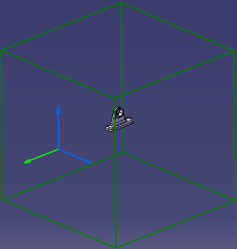

When no reference plane or surface is selected from 3D, then the view bounding box dimensions are computed from the standards, see Layout Views Customization. -
Select a plane to define the Front view plane orientation in the current scenario.
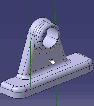
The view box is resized according to the 3D model.
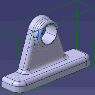

- You can orientate the view bounding box using the robot.
- You can modify the view bounding box angle using the green knob displayed on the robot, when you select a reference and when the Change primary view plane option is selected, see Primary View settings.
-
Select Left and Top views to be created in the Principal View dialog box and click OK.
Additional views are displayed in the specification tree.
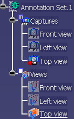

- Created view/annotation planes are typed as Projection View/Annotation and their reference planes are the faces of the bounding box.
- Captures are automatically created and associated with the related views. Names are the same for views and captures, by default. However, any modifications done in the view names are not reflected in the capture names.
- If No name check option is cleared in Tools > Options > Part Infrastructure > Display tab, Checking Operation when Renaming area, a check is performed to ensure that two views do not bear the same name in a given annotation set. If a view with the same name already exists in the annotation set, the previous view name is restored, and an information message is displayed.