However, note that when selecting background elements you cannot detect surface or silhouette edges or bodies. The elements taken into account of the background are all 3D points, vertex, curves, edges visible through edited sketch’s view background.
Background Elements
Using smartpick, you can directly select the background elements like an existing geometry of a sketch to position the future geometry to create.
|
|
To enable the detection of background elements via the SmartPick, select the Background elements check box available under Snapping in the Tools > Options > Mechanical Design > Sketcher > Constraint > SmartPick dialog box. |
You can select the background entities in geometry creation commands
and contextual commands as explained in
Creating Geometry Using SmartPick.
However, note that you cannot select the background elements while using
the following commands:
- Bi-Tangent Line
- Tri-Tangent Circle
- Conic
- Connect
- Corner
- Chamfer
- Close
- Complement
- Quick Trim
- Autosearch
The following commands directly manage the selection of background entities. This means that when creating a new geometry, you can define inputs by picking the background elements.
|
Also note that the following transformation commands Translate,
Rotate, Scale will not transform background
elements but their transformations can be defined using Smartpick on
background elements. Similarly, Break, Trim
couldn’t be applied to the background elements, but the operation can be
defined relying on a background element.
The following commands already use background elements by the creation
of use-edges geometries in the sketch:
|
|
|
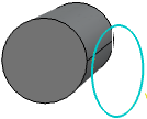
When smartpicking background elements, an edge is highlighted when moving the pointer over an edge of the surface, and also the different sketch's geometries or background elements defining detected constraints. |
Constraints
You can create constraints automatically while snapping the geometry to the background elements. To enable detection and creation of constraints over the background elements, select the Background elements check box available under Snapping in the Tools > Options > Mechanical Design > Sketcher > Constraint > SmartPick dialog box.
The number of background elements considered for snapping depends upon the Snap mode selected under under Snapping in the Tools > Options > Mechanical Design > Sketcher > Constraint > SmartPick dialog box.
The Creates the geometrical constraints check box
available under
Tools > Options > Mechanical Design > Sketcher >
Constraint must be selected.
Also note that, the background elements cannot be selected when doing a
trap selection and when the following visualization filters are
activated:.
|
General Behavior of Background Elements
The nature of a projected element can differ from that of the original background element. For example, a circle can be projected as an ellipse or a line.
Also the position of the projection can be different when sketch’s plane is not coplanar with the support of background element and the sketch's view is not normal to the sketch’s support plane.