Scaling elements also means re-computing distance values, if needed. Note that angle values will not be modified. Be careful: only non-fixed elements are updated.
-
Click Scale
 .
.
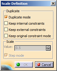
You can first select either the geometry or icon. If you select the icon first, you cannot multi-select elements. The Scale Definition dialog box appears.
-
Keep Duplicate mode selected.
The option is selected by default, which means that the 2D elements you select are copied.
Apart from the Duplicate mode option, the Keep internal constraints, Keep external constraints, and Keep original constraints mode options are cleared, by default.
However, after you execute this command, your chosen preferences are stored and used as the default options for the next usage. -
Select Keep internal constraints.
This option specifies that you want to preserve the internal constraints applied to the selected elements in scaling. -
Select Keep external constraints.
This option specifies that you want to preserve the external constraints applied to the selected elements in scaling.
If you clear this option, any external constraint existing between the selected elements and external elements will be disregarded in the scaling. -
Select Keep original constraints mode.
This option specifies to preserve the original constraints applied to the selected elements in scaling. The constraints defined in the original geometry are driving constraints. These constraints are copied to the scaled geometry as is (because the Original constraints mode option is selected). -
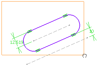
Select the elements to be scaled.
-
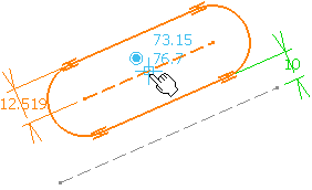
Click to indicate the center point on the geometry.
You can define the center point from its coordinates in the Sketch tools toolbar fields.
-
In the Scale Definition dialog box, type 2 as the scale value.
If required, you can select the Step mode option which controls the increments by which the scale value changes. -
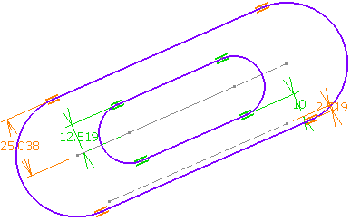
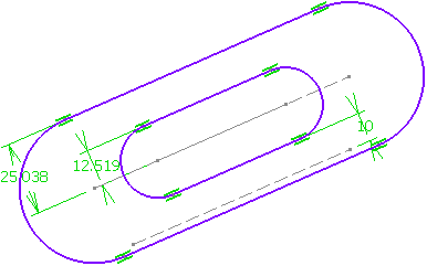
Click OK to confirm.
Internal constraints are preserved but revalued. As for external constraints, geometrical constraints are deleted, dimensional constraints are modified and revalued.
-
Click anywhere in the graphic area.
- If you clear the Original constraints mode
option, the geometry is scaled without preserving the
original constraints mode (driving/driven) as shown below.
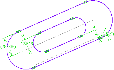
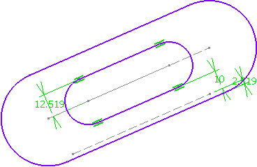
The constraints defined in the original geometry are driving constraints. These constraints are not copied in the resultant geometry (because the Original constraints mode option is cleared) which shows reference constraints. - If you clear the Keep internal constraints
option keeping Original constraints mode
selected, the internal constraints are not copied in the
resultant geometry as shown below:
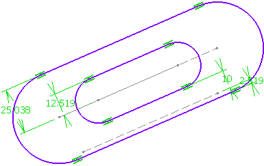
- If you clear the Keep external constraints
option keeping Original constraints mode
selected, the external constraints are not copied in the
resultant geometry as shown below:
- If you clear the Original constraints mode
option, the geometry is scaled without preserving the
original constraints mode (driving/driven) as shown below.
More about Step Mode
You can enable the
Step mode
option in the dialog box to increment scale
value by steps.
Note: To change the step value, right-click the value field and select
Change step > xxx mm.
For more information about parameter management which is common to all
parameters used in CATIA products, see CATIA Infrastructure User's
Guide: Using Knowledgeware Capabilities:
Parameters.