- Creating a Curvilinear Distance Constraint by using the Constraint Command
- Creating a Curvilinear Distance Constraint by using the Constraints Defined in Dialog Box Command
- Required Parameters
- Inconsistent Constraints
- Setting Curvilinear Constraints on an Arc of a Use-edge
Creating a Curvilinear Distance Constraint by using the Constraint Command
This task shows you how to create a curvilinear distance constraint by using two points and a curve.
-
Select two points.
-
Select the curve. In this case, select the spline.
-
Click Constraint
 on the Constraint
toolbar.
on the Constraint
toolbar.
The curvilinear distance value appears.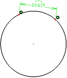
-
Position the dimension or click anywhere in the geometry to end the command.
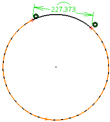
Before finishing the creation of the constraint, you can right-click on the constraint and select Toggle to switch the direction in which the curvilinear distance is measured.

You can switch the direction in which the curvilinear distance is measured, only for the periodic curves. The curvilinear distance constraint value is positioned. A CurvilinearDistance.x node is created under the Constraints node in the Tree. If necessary, an implicit constraint is created between point and curve, forcing the points to be coincident with the curve.
- You can click Tools > Options > Parameters and Measure > Constraints and Dimensions and modify the display parameters of the constraint.
- When you edit a constraint, you can set the curvilinear distance constraint as reference. In this case, the constraint value appears between parentheses to indicate that the constraint is a measure.
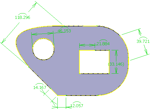
- If you select a single spline and then click Constraint
,
then, a reference curvilinear distance is automatically created
on the limit points of the curve, indicating the total
curvilinear length of the curve.
-
Optional: Perform the following actions to modify the constraint.
- Double-click the constraint.
The Constraint Definition dialog box appears with displaying the curvilinear distance value. - Click More to view additional information.
- Click the Point.x component in the
Supporting Elements area.
The related geometry is highlighted. - Click Reconnect... to redefine the constraint component.
- Select a different point and click OK.
The distance constraint is modified accordingly. - Right-click the constraint and select
CurvilinearDistance.x >Toggle to change the direction
in which the curvilinear distance is measured for the periodic
curves.
- Double-click the constraint.
Create a Curvilinear Distance Constraint by using the Constraints Defined in Dialog Box Command
This task shows you how to create a curvilinear distance constraint between two points and a curve by using the Constraints Defined in Dialog Box command.
Create a spline and two independent points.
-
Select two points.
-
Select the curve. In this case, select the spline.
-
Click Constraints Defined in Dialog Box
 on the
Constraint toolbar.
on the
Constraint toolbar.
The Constraint Definition dialog box appears.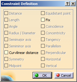
-
Select the Curvilinear distance check box and click OK.
The distance between the points is measured along the curve, and the constraint value is displayed.
-
Optional: Perform the following actions to modify the constraint.
- Double-click the constraint.
The Constraint Definition dialog box appears displaying the curvilinear distance value.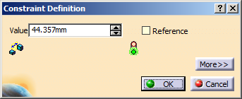
- Click More to view additional information.
- Click the Point.x component in the
Supporting Elements area.
The related geometry is highlighted. - Click Reconnect... to redefine the constraint component.
- Select a different point and click OK.
The distance constraint is modified accordingly. - Right-click the Value box and select
Edit formula.
The Formula Editor dialog box appears.
- You can also right-click the curvilinear distance constraint displayed in the Tree or the geometry and select CurvilinearDistance.x object > Edit Formula.
- If you want to create the constraints
permanently, click either Dimensional
Constraints
 or Geometric Constraints
 in the Visualization toolbar
depending on the type of constraint that you
want to create. If you do not click either
Dimensional Constraints
or Geometric Constraints
,
the constraints are created temporarily.
in the Visualization toolbar
depending on the type of constraint that you
want to create. If you do not click either
Dimensional Constraints
or Geometric Constraints
,
the constraints are created temporarily.
- Change the mode of the constraint and the activity type,
and Click OK.
For more information about knowledge parameters, refer to Knowledge Basics User's Guide. - Click Swap location.
The orientation of the constraint is inversed. The second input point moves to the other side of the first input point and the shape of the curve and the constraint value are modified. - Right-click the constraint and select CurvilinearDistance.x >Toggle to change the direction in which the distance is measured for the periodic curves.
The curvilinear distance constraint becomes inconsistent if either the curve's support cannot be extrapolated or both points are out of limit of the curve. - Double-click the constraint.
Required Parameters
When creating a curvilinear distance constraint, you must provide two points, a curve, and a distance value as inputs.
Consider the following conditions while selecting points.
|
Consider the following conditions while selecting a curve.
|
Consider the following conditions while providing the input value.
|
Inconsistent Constraints
An inconsistent constraint is created if an input point is defined out of limits of the parametric space of the curve.
The curve’s support is used to compute the curvilinear distance constraint, which means that the points may be present on the support, but are out of limits of the curve.
In case of a spline, the constraint is inconsistent if the curve’s support cannot be extrapolated.
In case of an arc, the support is a circle wherein both points of the curvilinear distance constraint can be defined out of limit points of arc. In this case, the constraint created is valid.
Setting Curvilinear Distance Constraints on an Arc of Use-edge
-
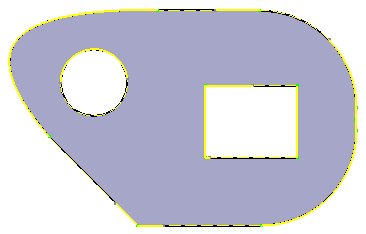
Using the commands for projecting 3D elements, create the use-edges of the 3D part representation.
The use-edges are created. They are represented in yellow color. -
Click Trim
 on the
Operation toolbar.
on the
Operation toolbar. -
Trim the use-edge to resize it as required.
The arc of use-edge is created and listed in the specification tree.
-
Click Constraint
on the Constraint toolbar. -
Select the arc of use-edge.
The curvilinear distance constraint is created between the end-points of the arc.
The curvilinear constraint is denoted with an arc of a circle above the constraint value.Arc of Use-edges with curvilinear distance constraints