In this scenario, the geometry is simply moved. But note that you can also duplicate elements with the Rotation command. You can de-activate the duplicate mode if needed by: De-activate Duplicate mode.
Rotating elements also means re-computing distance values into angle values, if needed. Be careful: only non-fixed elements are updated.
-
Click Rotation
 from the Operations toolbar (Transformation
subtoolbar).
from the Operations toolbar (Transformation
subtoolbar).
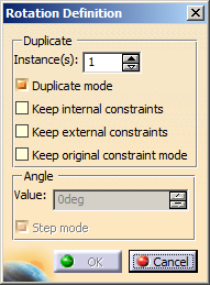
The Rotation Definition dialog box appears and will remain displayed all along the rotation. De-activate the Duplicate mode, if needed.
-
In the Instance(s) box, keep 1 as the number of instances to be created.
This option allows you to define the number of instances you want to create. -
Keep Duplicate mode selected. The option is selected by default, which means that the 2D elements you select are copied.

Apart from the Duplicate mode option, the Keep internal constraints, Keep external constraints, and Keep original constraints mode options are cleared, by default.
However, after you execute this command, your chosen preferences are stored and used as the default options for the next usage. -
Select Keep internal constraints.
This option specifies that you want to preserve the internal constraints applied to the selected elements in rotation. -
Select Keep external constraints.
This option specifies that you want to preserve the external constraints applied to the selected elements in rotation.
If you clear this option, any external constraint existing between the selected elements and external elements will be disregarded in the rotation.
ds -
Select Keep original constraints mode.
This option specifies to preserve the original constraints applied to the selected elements in the rotation. The constraints defined in the original geometry are driving constraints. These constraints are copied to the rotated geometry as is (because the Original constraints mode option is selected). -
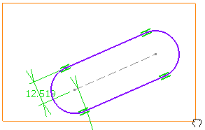
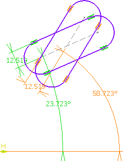
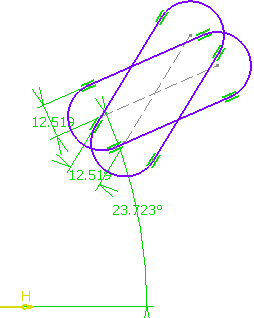
Select the geometry to be rotated. Here, select the entire profile.
-
Select or click the rotation center point.
You can also enter a value in the fields displayed (Sketch tools toolbar).
-
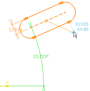
Select or click a point to define the reference line that will be used for computing the angle.
-
Move the pointer to get the required rotation angle.
-
Select or click a point to define an angle.
-
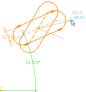
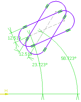
Click anywhere in the graphic area.
Internal and external constraints are preserved.
Rotating elements also means re-computing distance values into angle values, if needed. Be careful: only non-fixed elements are updated.
- If you clear the Original constraints
mode option, the geometry is rotated without
preserving the original constraints mode (driving/driven) as
shown below.
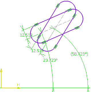
The constraints defined in the original geometry are driving constraints. These constraints are not copied in the resultant geometry (because the Original constraints mode option is cleared) which shows reference constraints. - If you clear the Keep internal
constraints option keeping Original constraints
mode selected, the internal constraints are not copied
in the resultant geometry as shown below:
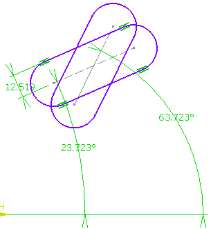
- If you clear the Keep external
constraints option keeping Original constraints
mode selected, the external constraints are not copied
in the resultant geometry as shown below:
- If you clear the Original constraints
mode option, the geometry is rotated without
preserving the original constraints mode (driving/driven) as
shown below.
- If you have selected step mode in the dialog box and set the value to 5 degrees, then when you drag the cursor to rotate the element it rotates by 5 degrees steps.
- You can also enter a value for the rotation angle in the Rotation Definition dialog box.
- Internal constraints are preserved
- External constraints:
- geometrical constraints are killed
- dimensional constraints are modified and revalued.
More about Snap Mode
You can enable the
Snap mode
option in the dialog box to increment rotation angle
value
by steps.
Note: To change the step value, right-click the value field and select
Change step > xxx mm.
For more information about parameter management which is common to all
parameters used in CATIA products, see CATIA Infrastructure User's
Guide: Using Knowledgeware Capabilities:
Parameters.