 |
This task shows how to create standard
elements or construction elements. Note
that creating standard or construction elements is based upon the same
methodology. |
 |
If standard elements
represent the most commonly created elements, on some occasions, you will
have to create geometry just to facilitate your design. Indeed,
construction
elements aim at helping you in sketching the required profile. |
 |
-
Click Standard/Construction
 from the Sketch tools toolbar so that the elements you are now
going to create be either standard or construction element.
- In this task, you will transform the newly created elements into
construction elements.
|
 |
- To see the construction elements outside sketcher,
select Add construction geometries for the newly
created sketch check box under Tools > Options
> Mechanical Design > Sketcher > Sketch Plane.
These elements appear as gray dashed lines and their
graphic properties are not editable.
- You can also display or hide the construction elements
for an individual sketch. To do so, right-click the sketch
feature in the tree and select Sketch.x object > Add
construction geometries/Remove construction geometries.
- If a sketch containing construction elements is selected
as an input for feature creation,
- Although the construction elements are made
visible outside Sketcher, they are not
considered for creation of sketch based features
such as pads and pockets.
- If the selection contains a combination of
standard and construction elements, then only
standard elements are considered for feature
creation.
- If the selection of construction elements
does not lead to any standard elements in the
sketch, then the construction elements (only
vertices and edges) can be used to create
features.
- The selected construction elements can be
forced to be used for feature creation, with the
help of user selection filters, such as the
point filter, curve filter, and geometrical
selection filter.
|
|
|
|
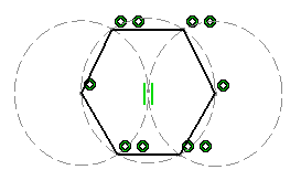
Here is an example of the use of both types of elements.
The hexagon was sketched using three construction circles: |
 |
|
This type of sketch is
interesting in that it simplifies the creation and the ways in which it is
constrained. Setting a radius constraint on the second circle is enough to
constrain the whole hexagon. Just imagine what you would have to do to
constrain hexagons sketched with no construction circles! |
 |
Standard or Construction Points
Points are represented either by crosses or just by points, depending on
the chosen creation mode.
- In standard mode, which is the default mode, points created on a
line, for instance, are represented by crosses. The points and the line
are visible outside the Sketcher workbench.
- Points generated by Break operations are created in construction
mode, even if Standard/Construction
 is set to Standard.
|
 from the Sketch tools toolbar so that the elements you are now
going to create be either standard or construction element.
 is set to Standard.