Annotation Parameters

The annotation parameters are located in the Annotation node of the Standard Definition editor. They deal with the position of text leaders and annotation blanking parameters. 

Note: The parameters which allow you to customize annotation leader symbols are located in the Dimension node of the standard editor. The parameters located in the Dress-Up node let you customize the appearance of dress-up elements, such as markup arrows and threads.


These parameters depend on a given parent standard. 

Annotation Texts

Parameter

Description

Parent standard 

Value

Description

Text > Leader Gap

Horizontal offset between the text and the leader extremity 

ANSI and ASME only

(mm)

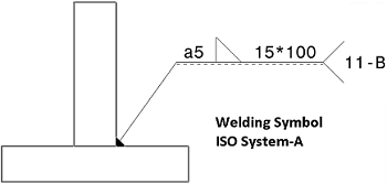
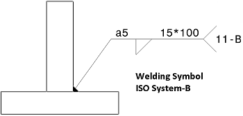
Text > Leader Vertical Space

Vertical offset between the bottom of the text and the horizontal part of the leader

Note: If you are a DS Passport customer, you can read the QA00000010089 article from the Knowledge Base for more about the leader vertical space.

ISO and JIS only

(mm)


Surface Texture

Parameter

Description

Parent standard 

Value

Description

Surface Texture > Layout

Layout of the surface texture

All standards

Authorized / Not authorized

Specifies whether a given field should be displayed (Authorized) or hidden (Not authorized) in the Surface Texture dialog box


Surface Texture > Leader Gap

Horizontal offset between the surface texture and the leader extremity 

ANSI and ASME only

(mm)

Surface Texture > Leader Vertical Space

Vertical offset between the bottom of the surface texture and the horizontal part of the leader

All standards

(mm)


Surface Texture > Extension Line > Thickness > Behavior

Behavior of the extension line thickness

All standards

Fixed / Variable with symbol

Specifies whether the thickness of the extension line should be fixed (using the value specified by the Line Thickness parameter below) or variable (using the graphic property of the thickness symbol itself).

Surface Texture > Extension Line > Thickness > Line Thickness

Extension line thickness index

All standards

Integer

Specifies the line thickness index (as defined in the LineThickness node of the current standard) that should be used to represent the extension line. This parameter is taken into account only if the Behavior parameter is set to Fixed.

Surface Texture > Extension Line > Gap to surface

Extension line gap to surface

All standards

(mm)

Specifies the gap between the extension line and the pointed object.

Surface Texture > Extension Line > Length according to symbol

Extension line length defined according to symbol or not

All standards

Yes / No

Specifies whether the extension line length should be defined according to the surface texture length.

With value set to Yes:

With value set to No:

Surface Texture > Extension Line > Overrun

Extension line overrun

All standards

(mm)

Specifies the overrun of the extension line.

When Length according to symbol parameter is set to Yes:

When Length according to symbol parameter is set to No:

Surface Texture > Leader anchor according to standard (for ANSI and ASME)

Leader anchor

ANSI and ASME only

Yes/No

In case of ANSI or ASME standard, specifies whether the surface texture leader anchor parameter should be the normalized standard, i.e. the Leader Vertical Space parameter (with value set to Yes) or the Leader Gap parameter (with value set to No).


Blank Background

Parameter

Value

Description

Blank Background > Around Value > Extend to Frame

Yes / No


Blank Background > Around Value > Margin

(mm)

Default value is 1 mm.

Blank Background > Around Symbol > Activated

Yes / No


Blank Background > Around Symbol > Margin

(mm)

Default value is 0.5 mm.

Blank Background > Around Symbol > Margin Around Sensitive Point

(mm)

Default value is 0.2 mm.
All the geometries in the green zone will not be blanked.


Welding

Parameter

Value

Description

Welding Staggered Display

Usual/Alternative

Usual - Adds the staggered (Z) symbol in the welding symbol.
Alternative - Offsets the welding symbols on the opposite side of the reference line.

Welding Staggered Display Offset

(mm)

Specifies the welding symbol offset.
By default, the value is 5 mm.

Welding Display > System-A  

The symbolic representation of this system is based on a double reference line: a continuous line and a dashed line.

Welding Display > System-B  

The symbolic representation of this system is based on a unique reference line.

Overrun By default, the value is 1.0 The overrun is equal to the font size.
Flag Display > Parameter 1 By default, the value is 1.5
Flag Display > Parameter 2 By default, the value is 0.5
Flag Display > Parameter 3 By default, the value is 0.8


Tolerance

Parameter

Value

Description

Intersection Plane

Yes/No

Select Yes to add to the list of Auxiliary Feature Indicators in the Geometrical Tolerance dialog box.

Orientation Plane

Yes/No

Select Yes to add to the list of Auxiliary Feature Indicators in the Geometrical Tolerance dialog box.

Collection Plane Yes/No Select Yes to add to the list of Auxiliary Feature Indicators in the Geometrical Tolerance dialog box.
Direction Feature Yes/No Select Yes to add to the list of Auxiliary Feature Indicators in the Geometrical Tolerance dialog box.

The default values are Yes for ISO and JIS standards and No for ANSI-ASME standard.