-
Pick twice a surface boundary or a wire.
- The results of the picks are points on a curve, at a distance of a vertex.
- You can drag a point, possibly on a vertex (The geometry is automatically updated).
- The two picks can be on the same or on two related supports.
- You can also select the start or end of existing stable split curves.
- They are the start and the end of the stable split curve.
- At any time, you can delete one point and select another.
-
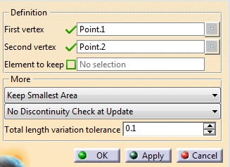
Alternatively, select two vertices or an edge before starting Stable Split Curve.
The boundary or wire is split by the vertices. By default, the smallest area is proposed as the stable split curve, displayed as a dotted blue line.
Note: If the design changes (For example, if the surface is replaced by another one), the points are re-computed. -
Enter a Total length variation tolerance.
A warning is displayed if the length variation of the stable split curve during a design change exceeds the specified value
Note: Basically, the stable split curve is defined by two points on a join with a support surface.
Replacing the support surface by a more complex one may prevent the B-Rep re-computation of the points.
In that case, the input vertices are projected on the nearest support.
If the new surface is a translation of the initial one in the normal direction, the projection is correct.
Otherwise, the re-computation fails. -
Under More, specify the area to keep.
- Keep Smallest Area (Default choice)
- Keep Largest Area
- Keep from Element: Select an element to specify the area to keep.
-
Specify the type of discontinuity to check at update (None, G0, G1 or G2).
A warning is displayed if a discontinuity if found.
A Stable Split Curve feature is created under Local Tool Set, in Selection Tools Set.
![]()