Chaining Edges and Minimize Angle
-
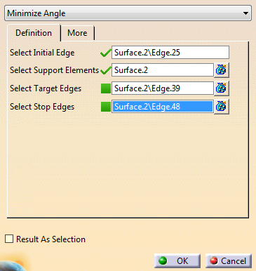
Select the initial edge.
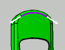
It is displayed in purple, with two direction arrows.
-
Click an arrow to indicate the direction and start the propagation.
-
Optional: To help propagation computation:
- Select target edges. They are displayed in green.
- Select stop edges. They are displayed in yellow.
- If propagation reaches a target or a stop edge, it is automatically selected.
- Propagation stops when a stop edge is reached.
- Propagation does not try to reach target or stop edges, it uses them when reached.
-
Go to the More tab to set the tolerance
G0 Tolerance: If the distance between two edges is lower than this value, they are considered as connected, propagation goes from one to the other.
-
Still in the More tab, review the list of points where propagation made a decision not related to G1 continuity.
As you select a line in the table, the point is displayed in the work with some information. -
Optional: Activate Result As Selection.
Useful to create a Generative Shape Design join or modify the visual properties of faces.
No feature is created, the result is a selection of faces.
Chaining Edges and Inner Curve Beween Points
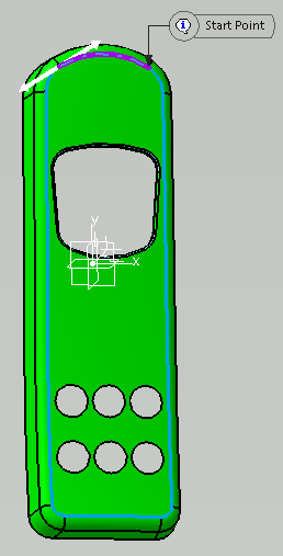
You can select edges between two points of a boundary. The edges are inner edges, that is not on the boundary of the selected support.
Use this mode to define areas on a surface, such as the flanges in Die Face Design.
Note: To guarantee stability when design changes:
- The start and end points are automatically projected on the boundary.
- If the original BRep is lost, the last stored position is used.
- If the passing edges are not found, the closest edge on the new support is used.
-
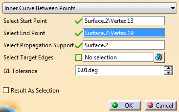
Select Inner Curve Beween Points in the list.
-
Select one start and one end point on the boundary.
-
Select target edges.
Propagation goes through them whenever possible. -
Set the Tolerance.
G1 Tolerance: If the tangency discontinuity between two edges is lower than this value, they are considered as tangent. They are given propagation priority.
A Chaining Edges feature is created (Unless Result As Selection is activated), with its tolerance parameters and total length.
![]()