- reconstruct them using the Fillet Radius Reduction command, or in some cases, other commands such as fills.
- or color them to be used later on by color-based commands.
Be aware that:
- Not all fillets can be detected nor can be reconstructed.
- Orange and red colors are used for warnings:
- Orange indicates there is a variation in the fillet radius. It is up to you to decide wether the element is a fillet or not.
- Red indicates surfaces with invalid edges, as explained below.
It is not possible to have an overview of the size of the fillets of a model: you must be familiar with the model, or work by trial and error. We recommend that you handle first the fillets that are easy to recognize, and then that you handle more complex areas.
- This command is available on a part level only.
If you are working in an assembly, make current the part containing the surfaces to analyze. - This command aims at detecting four-sided fillets, with a constant
radius:
- Three-sided junctions of fillets are not detected.
Fillets finishing in a triangle are not detected, at least whenever they have only three sides.
We recommend that you recreate those fillets as fills. - The notion of number of sides is based on geometric considerations: two adjacent edges of the boundary are not in the same side if thy form a sharp angle. Sometimes, a face may be seen as having three sides, whereas it has more than three sides, geometrically speaking.
- Fillets with variable radius are not dealt with.
- Three-sided junctions of fillets are not detected.
- This command can detect concave or convex fillets with respect to a
stamping or pulling direction:
- You must ensure that the surface to analyze
does not present undercut areas with respect to this direction
(stamping or pulling direction) otherwise the criterion concave or convex will have no meaning in the current context.
- You must ensure that the surface to analyze
does not present undercut areas with respect to this direction
- You have to choose the best direction for the search.
In most cases, the direction to use is the pulling direction (plastic injection) or the stamping direction. - Search Fillets creates a join per interval found and per
area of connected surfaces.
Below is an example of joins created on two areas.
Then the validity of the join edges is checked.
When invalid edges are found, the surfaces are put into a sub-geometrical set named yyyNoJoin.x and the faces are displayed in red.
- We recommend that you use one single interval with the smallest possible interval values or the detection of fillets. Regrouping fillets of different sizes in a single geometrical set can make the analysis of the result difficult.
- The command may detect faces as candidate fillets, although they are
not fillets:
- This occurs because the geometry analyzed is not precise enough,
- The analysis is done face by face.
Often a visual inspection of the neighboring faces will tell you whether a face was intended to be a fillet or not.
Therefore, you should remove faces that you know are not fillets from the selection to analyze. - Simply click a face to remove it from the result selection.
-
Click Search Fillets
 in the Modify Fillet Radius toolbar.
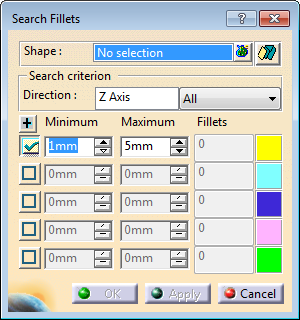
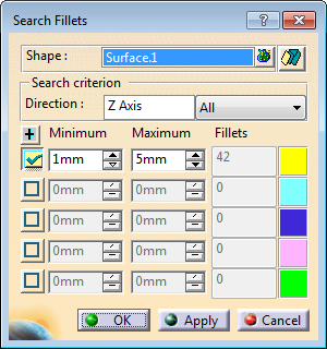
The Search Fillets dialog box is displayed:
-
Multi-selection is available. - Click
 to display the list of elements selected.
 - Click an element in the graphic area or in the specification tree to add it to the selection list.
- Select an element in the list, and click Remove to modify the selection list.
- Click Reset to clear the selection list.
- Click Close to end the selection and revert to the main dialog box.
- Click
-
Define the type of output by clicking:
-
 :
the output is a color attribute.
:
the output is a color attribute. -
 :
the output is colored extracts.
:
the output is colored extracts.
-
-
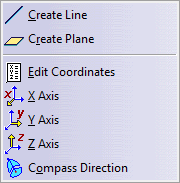
Optional: Define the Direction of search.
- Select a line to take its orientation as the search direction,
- or select a plane to take its normal as the search direction,
- or use the Direction contextual menu:
-
Optional: select the type of fillets to search:
- All
- Concave
- Convex
-
Select as many Interval lines as you need, and key in the Minimum and Maximum radius values of those intervals.
Click + to display more intervals.
-
Click Apply.
The number of fillets found on each interval is displayed in the dialog box.
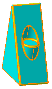
The fillets are highlighted in the corresponding color:
-
Double-click a color patch to launch the color editor and edit the color of the fillets found in this interval.
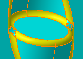
Take advantage of the color to analyze the result of the search:
In the image below, it is easy to see that some faces have been missed by the search, and that you need to extract them to complete the fillet.
-
Click OK.
If you have selected,
the fillets found are colored:
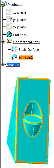
If you have selected:- A geometrical set is created for each interval.
- Its name is made of Radius followed by the radius value of the interval.
- The fillets are created with the color
corresponding to the interval in the dialog box.
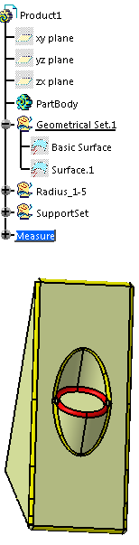
The fillets found in a given interval are extracted as RadiusExtract.x in feature mode or RadiusSurface.x in datum mode and placed in the geometrical set created for this given interval. - The input surface is sent to the NoShow.
- A geometrical set named SupportSet is created with the faces of the input surface that are not candidate fillets, gathered in connected surfaces.
- The collection of SupportSet and of all the Radiusxx geometrical sets represents precisely the entire input model.
![]()