Definition
Hidden Line Removal (HLR) lets you print in vector mode the viewed edges and outlines of 3D objects. It is an extension of the Wireframe rendering mode where (or segments of lines) visually occluded by surfaces are not drawn. Note that in HLR mode, the color of drawn edges is the color of the surface they belong to.
About HLR Algorithms
Two HLR algorithms can be used to compute a HLR scene:
- Exact mode which uses exact geometry
- Polyhedral mode which enables to compute HLR on non-exact geometry that can be found in third-party data, in CGR files (when working with the cache system, for instance) or in specific Version 4 elements.
The Exact mode is more CPU- and memory-intensive than the Polyhedral mode but gives a more accurate result.
HLR and Dynamic Hidden
Line Removal (HRD) are not computed the same way because
HRD is primarily based on the
graphics card. Therefore, discrepancies might appear
between the two results.
For instance, on screen in 2D Layout for 3D Design
in HRD mode, the intersection profile of an
object with a front cutting plane or a back clipping
plane is not displayed. However, the HLR print
result shows this intersection profile:
| Shading with Edges | HRD | HLR |
 |
 |
 |
Regarding transparent faces, HLR algorithms consider them as opaque which means that objects behind these faces are hidden. On the contrary, the HRD rendering mode considers transparent faces as completely transparent by default. To force the HRD mode to consider transparent faces as opaque, use the Display transparent faces as opaque option in Tools > Options > General > Visualization.
Linetype
From V5R18, the linetype and the line thickness of drawn edges are taken into account in HLR rendering mode. This means that the linetype displayed in the print preview is the one you see in the geometry area. For instance, if the linetype is defined as "empty", edges will not be displayed.
Restrictions
Note that:
- HLR behaves badly when the Display all elements using Z-buffer depth option is selected in Tools > Options... > General > Display > Visualization.
- HLR behaves badly with points, certain kinds of line, texts and images as soon as they are in Z mode (i.e. they participate in the Z-buffer).
- Smooth edges cannot be removed when using
HLR if the three following conditions are
fulfilled at the same time:
- The model has been designed in Version 5 (e.g. a CATPart).
- The model was first created before V5R16.
- The V5 session uses the cache management option OR only the CGR file of the CATPart model is inserted in the Product, not the CATPart itself.
- Smooth edges cannot be removed when using HLR if the window viewpoint is CONIC.
Exact mode
As this mode is based on exact geometry, the result
is more precise. However as explained above, this mode
is CPU- and memory-intensive and some restrictions might
occur in specific cases.
For instance, you might encounter problems with clashing
bodies because some geometrical elements might not be
generated. To by-pass this limitation, you can manually
resolve the intersection topology using an appropriate
sequence of Boolean operations.
Polyhedral mode
In this mode, the geometry's complexity (in terms of number of triangles for each face of a surface) is limited. Attributes applied to edges, such as the linetype or the thickness, are those of the original edges as far as possible. When it is not possible to use the original attributes, default attributes are applied instead.
Regarding clashing bodies, the Polyhedral HLR mode is a lot more robust than the Exact mode although it does not strictly support all clashing configurations.
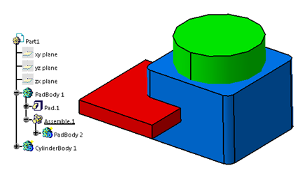
Example
| Exact Mode | Polyhedral Mode |
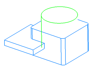 |
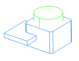 |
| On top of the green cylinder, the Exact mode avoids SAG effects on printed curves. | The clash between the green and blue bodies is supported in Polyhedral mode only. |
The result of the Boolean operator between the two blue pad bodies is supported in both Exact and Polyhedral modes:
Behavior in Specific Applications
When working with the Clipping > Activating clipping frame, the Clipping > Clip View or the Insert > Sectioning command in a 2D Layout for 3D Design or DMU Sectioning context, the polyhedral HLR mode is used. See the Version 5 - 2D Layout for 3D Design User's Guide for more information about clipping commands and the Version 5 - DMU Sectioning User's Guide for more information about sectioning.