This task shows how to create a surface by revolving a planar profile about an axis.
Open the Revolution1.CATPart document.
-
Click Revolve
 .
.The Revolution Surface Definition dialog box appears. -
Select the Profile and a line indicating the desired Revolution axis.
-
For Limit 1 and Limit 2, specify the limit types of the revolution.
Dimension: Enter angle values or use the graphic handles to define the start and end limits of the revolving profile.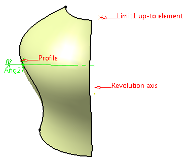
Up-to element: Select a geometric element. It can be a point, a plane, or a surface. If a point is specified, the up-to element is the plane normal to the revolution direction passing through the given point.
In the angle box, enter a value to define an angular offset from the selected up-to element.
Note: Wires cannot be selected as an up-to element -
Click OK to create the surface.
The surface (identified as Revolute.xxx) is added to the specification tree. 

- There must be no intersection between the axis and the profile. However, if the result is topologically consistent, the surface will still be created.
- If the profile is a sketch containing an axis, the latter is selected by default as the revolution axis. You can select another revolution axis simply by selecting a new line.
- Parameters can be edited in the 3D geometry. To have further information, refer to the Editing Parameters chapter.
Revolute Up to point: Specific geometric case.
![]()