|
This task shows how to use create rectangular patterns,
that is to duplicate an original wireframe or surface-type element at the
location of your choice according to a rectangular arrangement.
This means that you will need to define a 2-axis system using two
directions. |
") |
Open the
Pattern1.CATPart document. |

|
-
Click Rectangular Pattern
 . .
-
Select the element you wish to replicate as a pattern.
| The Rectangular Pattern Definition dialog box is displayed. Each
tab is dedicated to a direction you will use to define the location
of the duplicated element. |
 |
-
Click the Reference element field and select a
direction to specify the first direction of creation.
 |
To define a direction, you may select a line, a planar face or
surface edge.
You can reverse this direction by clicking the Reverse button. |
-
Set the duplication parameters by choosing the number of
instances, the spacing between instances, or the total length of the zone
filled with instances.
Four options are available:
- Instance(s) & Length: the spacing between instances is
automatically computed based on the number of instances and the
specified total length
- Instance(s) & Spacing: the total length is
automatically computed based on the number of instances and the
specified spacing value
- Spacing & Length: the number of instances is
automatically computed to fit the other two parameters.
- Instance(s) & Unequal Spacing:the spacing
between instances is specified by the user. You can double-click
the spacing value in the geometry area to edit and modify it.
|
| For each of these cases only two fields are active,
allowing you to define the correct value. |
 |
If you set Instance(s) & Length
or Spacing & Length parameters, note that you cannot
define the length by using formulas. |
-
Click the Second Direction tab to define the
same parameters along the other direction of the rectangle.
 |
| You can delete instances of your choice when creating or editing
a pattern. To do so, just select the points materializing instances
in the pattern preview. |
| The instance is deleted, but the point remains, as you may wish
to click it again to add the instance to the pattern definition
again. |
 |
-
Click More>> to display further options.
| These options let you position the instances in relation to the
first selected element. |
 |
-
Increase the Row in direction 2 to 2.
| You notice that the first selected pattern now is the second
instance in the vertical direction, as this was the second selected
direction. |
 |
| Simplified representation lets you lighten the pattern
geometry, when more than 15 instances are generated. What you need to
do is just check the option, and click Preview. The system
automatically simplifies the geometry: |
 |
| Previewed simplified geometry |
| |
 |
| Simplified geometry |
| |
| You can also specify the instances you do not want to see by
double-clicking them. These instances are then represented in dashed
lines during the pattern definition and then are no longer visible
after validating the pattern creation. The specifications remain
unchanged, whatever the number of instances you view. This option is
particularly useful for patterns including a large number of
instances. |
-
Click OK to create the pattern.
| The pattern (identified as RectPattern.xxx) is added
to the specification tree. |
 |
|
|
- Patterning User Features (UDFs) is not allowed.
- You can cut or copy rectangular patterns provided it belongs to
the same body.
|
|
|
 |
| |
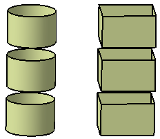
Patterning Volumes
|
|
|
This capability is only available with the Generative Shape Optimizer
product. |
|
|
Open the
PatterningVolumes1.CATPart document. |
|
|
-
Click Rectangular Pattern
.
-
Select the element you wish to replicate as a pattern.
| The Rectangular Pattern Definition dialog box is displayed. |
-
Click the Reference element field and select a
direction to specify the first direction of creation.
-
Set the duplication parameters by choosing the number of
instances, the spacing between instances, or the total length of the zone
filled with instances.
-
Click OK to create the pattern.
|
|
|
Creating Rectangular Patterns using Multiple Elements
|
|
|
You can create rectangular patterns using multiple surface or volume
elements, i.e. duplicate an original wireframe or surface-type element
at the location of your choice according to a rectangular arrangement.
For this you need to define a 2-axis system using two directions. |
|
|
Create a 3D shape
containing wireframe, surface or volume elements. |
|
|
-
In the 3D area, select all the surface (or volume)
elements that you want to replicate.
|
|
The selection should contain either all surface or all
volume elements. Mixed selections are unsupported. |
-
Click Rectangular Pattern
in the Replicate toolbar.
| The Rectangular Pattern Definition dialog box is
displayed with the Object box showing the number of
elements you selected in step 1. |
-
Optional: Click
 to edit the patterning elements.
The Object to Pattern dialog box is displayed.
-
Optional: Select an element in the list
and click either Remove or Replace to modify
individual pattern elements.
-
Optional: Click Close to
close the dialog box.
-
Specify the required inputs by referring the steps from 3
through 8 as explained in "Creating Rectangular Patterns.
-
Click OK to create the pattern with multiple
elements.
|
|
|