This task shows you how to create several points and planes at a time, and modify certain repetition parameters, such as instances and spacing.
Display the Points toolbar by clicking and holding the arrow from the Point icon.
Create Multiple Points and Planes
-
Click Points Repetition
 in the Replication toolbar.
The Points Repetition dialog box appears: 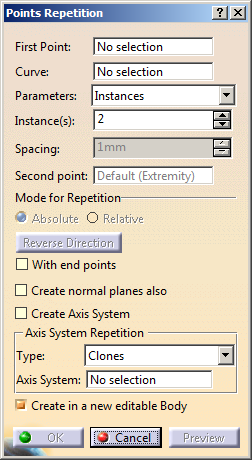
-
Select the Curve.

- If the First Point selected is of type On Curve, the Curve field is automatically updated with the underlying curve.
- If only the curve is selected to create multiple points on it, the First Point field is updated with Default Extremity and the Instances & spacing option is unavailable from the Parameters list.
- If the selected First Point is not of type On Curve (point created using the Datum mode for instance), you have to manually select a curve in the Curve field.
- If Clear Selection is selected from the contextual menu for First Point, and the point type is On Curve, the default curve selection will also be cleared.
-
Choose the side on which the points are to be created in relation to the initially selected point. Simply use the Reverse Direction button, or click on the arrow in the geometry.
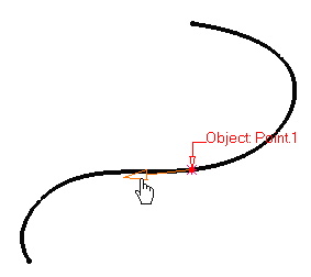
-
Select the repetition Parameters: Instances or Instances & spacing.
-
Define the number of points to be created in the Instance(s) field. Here we chose 5 instances.
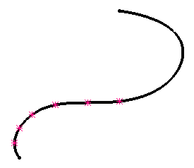
When you select a point on a curve, Instances & spacing is available from the Parameters drop-down list. In this case, points will be created in the given direction and taking into account the Spacing value.
For example, 3 instances spaced by 10mm.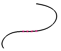
When you select Instances & spacing, you can choose the repetition mode:
- Absolute (default mode): the spacing value of the repeated feature directly refers to the spacing value of the parent feature.
-
Relative:
the spacing value of the first repeated feature refers to the
spacing value of the parent feature. Every next repeated feature
will refer to the spacing value of the previously created
feature.
A new parameter called "Relative Spacing" is aggregated under the repeated features in the specification tree (except for the first repeated feature). Therefore, every created repeated feature is created with the spacing value of the previous feature plus the "Relative Spacing" value.

The spacing value entered in the dialog box is taken as a reference for "Relative Spacing". Once the instances are created, you can edit the "Relative Spacing" value in the specification tree only. As a consequence, the repeated feature will move according to new value and further repeated features will be created or updated using this new value plus the "Relative Spacing" value of the parent feature.
When you select Spacing, you can create points or planes distributed over the whole length of the selected curve or from the selected point, respectively, according to the defined spacing. The number of created instances is indicated in the Instances box and cannot be modified.
-
Click Preview to view the point instances.
-
Select a second point in the Second point field.
This capability lets you define the area of the curve where points should be created.

If the selected point on curve already has a reference point (as described in Creating Points - on curve), this reference point is automatically taken as the second point. By default, the Second point is one of the endpoints of the curve. -
Select the With end points, check box to define the last and first instances are the curve end points.
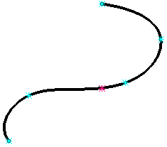
-
Select the Create normal planes also check box to automatically generate planes at the point instances.
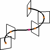
-
Select the Create in a new Body check box to create all object instances in a separate body. Otherwise the instances are created in the current body. A new geometrical feature set will be created automatically, depending on the type of body the points or planes to be repeated belong to.

In case an Ordered Geometrical Set is created, it is considered as private: it means that you cannot perform any modification on its elements (deleting, adding, reordering, etc., is forbidden).
If the option is not checked the instances are created, in the current body.
-
Click OK to create the point instances, evenly spaced over the curve on the direction indicated by the arrow.
The points (identified as Point.xxx as for any other type of point) are added to the specification tree.
- Selecting sub-elements of a feature (i.e. edges or faces) or of an axis system (i.e. xy plane) is not allowed.
- Performing a local Undo is not available with this command.
Edit Multiple Points and Planes
You can edit certain repetition parameters of multiple points and planes.
Edition of parameters is possible only if the Create in a new editable Body option is selected when creating multiple points and planes. |
-
Double-click the Repetition node in the tree.
The Points & Planes Repetition dialog box appears.
You can modify only the number of instances and spacing. Other parameters are unavailable for editing. -
In the Instances(s) box, enter the instance value or use the arrows to change the instance value.
If you increase the number of instances, new points are added. Old points are retained but their formula is re-computed.
If you decrease the number of instances, a warning message is issued.- Click Yes to delete the old points.
- Click No to remove the old points from the Repetition node and re-aggregate after the node.
-
Click OK to update the point instances.
Create Multiple Axis Systems
-
Select the Create Axis System check box.
The Points & Planes Repetition dialog box appears. -
In the Type box, select the desired repetition type.

- If you select Clones, you need to specify the reference axis system for cloning. The specified axis system is cloned on all the repeated points.
- If you select Along Surface, you need to select a surface. The axis systems are created with point on the curve as origin, line tangent to the curve as x-axis, and line normal to the surface as y-axis.
- If you select Directional, you need to select a direction. By default, z-component is selected as the direction. The axis systems are created with a point on the curve as origin, specified direction as z-axis, and the line tangent to the curve as the x-axis.
-
Click OK.