You simply activate Connect Checker while the Matching Constraints command is active.
-
Click the Matching icon
 .
.
The 'Matching Constraint' dialog box opens.
In the following example, we are going two match two surfaces.
-
Click on the Source surface near the edge you would like to match.
-
Click on the Target surface near the edge the Source surface has to snap to.
An arrow appears. Its origin marks the edge which will be matched.
-
Click Apply in the Matching dialog box to match the surfaces.
-
Undo the last step and click the arrow. The Target surface will now be snapped to Source surface.
Source and Target can also be inverted by the option Invert.
-
Click OK to match the surfaces.
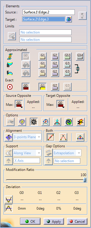
Elements
- Source: Selection of the element to be deformed to fulfill the requested conditions.
- Target: Selection of the target geometry which will not
be changed. You can select two surface edges or curves.
Datum and Feature point elements are also supported as target elements for G0 continuity.  Invert: Swap Source and Target.
- Limits:
 Partly: Allows to match
the source edge to part of the target edge.
Partly: Allows to match
the source edge to part of the target edge.
You can specify the limiting points via the selection fields.
The snap manipulator allows you to snap the vertex of the source element to a point.

Tip: For partial matchings, it is recommended to use Minimum Corner Distance in Tools > Options > ICEM Shape Design > General tab. In case of partial matching constraints, gaps or overlaps may occur if the source surface corners do not coincide with the target surface corners. With Minimum Corner Distance, a corner distance tolerance is specified.
If the source surface corner is moved with the manipulator, it automatically snaps to the corresponding target surface corner as soon as its position is within the distance from the target surface corner defined by the tolerance.
Approximated and Exact
For matching constraint of surfaces, two types of algorithm are available
which can be used together: the exact algorithm and the approximated algorithm.
If both of them are used, the first one to be performed is the exact one,
then the approximated.
For matching constraint of curves, only the exact
algorithm can be used.
- Approximated: The control point distribution in the first
control point row of the source element remains unchanged. This
may cause larger continuity deviations.
-
Orders of continuity: Specifies the matching transition.

 Begin and End Edge continuities (G3 in ISD
only): Aligns the cross tangents at the edges of the
source and the target.
Begin and End Edge continuities (G3 in ISD
only): Aligns the cross tangents at the edges of the
source and the target.
- Begin and End Edge continuities OFF: All cross tangents will be aligned coplanar only, i. e. there may be an angle between the cross tangents of the source and the target.
- Begin or End Edge continuities ON: The beginning or end cross tangent of the source will be aligned collinear to the beginning or end cross tangent of the target.
- Begin and End Edge continuities ON: All cross tangents of the source will be aligned collinear to the cross tangents of the target.
 Lock Boundaries: You can fix the selected
boundaries of the source element. Only the other
control points are moved. If both boundaries are
fixed, only inner control points are moved.
Lock Boundaries: You can fix the selected
boundaries of the source element. Only the other
control points are moved. If both boundaries are
fixed, only inner control points are moved.
Input geometry Lock Boundaries at end of edge Lock Boundaries at start and end of edge 
 Exact:
Defines the continuity in case of matching curves.
Exact:
Defines the continuity in case of matching curves.
In case of matching surfaces, the source element adopts the parametrization from the target element. Depending on the selected continuity, the control point distribution is influenced in the rows 1 (G0) to 4 (G3).
Exact OFF with G0 continuity Exact ON with G0 continuity 
- Opposite: You can change the continuity values to be kept at the opposite edges either via the context menu at the continuity labels in the work area or by these options in the dialog box. The values are automatically updated in the respective environment.
- Opposite Continuities:
- Source Opposite:

These options are available only if the Diffusion  option is selected.
Defines continuities to be kept at the opposite curve end or surface edge of the source.
When using Diffusion
option, control point/row modifications done to
achieve the continuity with the target is propagated to
other control points/rows than the ones directly involved by
the specified continuity. This may move control points/rows
at the opposite end or edge and thus modify the continuity
at the opposite end or edge.
At the opposite source curve end point or surface edge, you can specify a maximum continuity to be kept using either the Max. list in the dialog box or in the work area the context menu available at the continuity labels which appear when Diffusion
option is selected.
G0 continuity is set by default, but you can select any other continuity irrespective of whether the order allows to keep it or not. If the continuity cannot be kept, the maximum possible continuity is applied and displayed under Applied in the dialog box marked by asterisks in the context menu.
The Free option applies no continuity. This allows the movement of all control points or control point rows, without keeping any continuity, to obtain an optimal control point distribution with Diffusion
option. As in this case no continuity is kept at
opposite, the continuity with neighboring elements at the
opposite end point or edge may be broken.
- Matching constraints between source and target always have priority over the continuity specified at the opposite in case that both continuities cannot be kept.
- Create another matching constraint between the opposite end point or edge and the other target to manage the wanted continuity at the opposite with the same priority.
Also see, Mean Surface Solver option in Tools > Options > Shape > Freestyle, Matching Constraint command options section. - Target Opposite:
These options are only available if the following option are selected:
- Diffusion
- Under Both, either Mean
 or Extension

These options define continuities to be kept at the opposite curve end or surface edge of the target analogous to the Source Opposite options. - Diffusion
- Source Opposite:
 Inside: Projects the
edge of the source surface onto the target surface. On the target surface is displayed a preview of the edge position.
Inside: Projects the
edge of the source surface onto the target surface. On the target surface is displayed a preview of the edge position.
The direction depends on the Support option. Basic Surfaces: Provides the ability to match
a source surface to the underlying basic surface of a target
surface which is represented by a face.
Basic Surfaces: Provides the ability to match
a source surface to the underlying basic surface of a target
surface which is represented by a face.-
Diffusion: Modifies the maximum number of rows
of control points.
 Adapt: Adopts the order of the target edge from
the source.
Adapt: Adopts the order of the target edge from
the source. Display deformation distance: Displays the maximum
deviation value and its position between the original surface
and the modified surface in the graphic area. The original
mesh before the modification is also displayed.
Display deformation distance: Displays the maximum
deviation value and its position between the original surface
and the modified surface in the graphic area. The original
mesh before the modification is also displayed.
While using the command you can reset the reference. Right-click the arrow of the variant display and select Reset Delta Reference to reset the reference. The existing position of the surface is set as new reference. The reference mesh and the maximum deformation distance are computed with respect to the new reference. Auto Apply: Applies modifications automatically.
-
 No Highlight Representations: Deactivates the highlight
on the selected elements to avoid conflicts with the display
of other entities such as control points.
No Highlight Representations: Deactivates the highlight
on the selected elements to avoid conflicts with the display
of other entities such as control points. - 3-points Plane: Projection orthogonal of control points on a 3 points plane. For each control point row of the surface to match, a plane is defined from the 1st, the 2nd and the last control point. All points of each row are projected into its plane.
- Mean Plane: Projection orthogonal of control points on a mean plane. For each control point row of the surface to match a mean plane is defined, and all points of each row are projected into its plane.
-
Mean: In case of matching curves, the endpoints
of the input curves to be connected are moved to the midpoint
of their connecting line:
Curve matching with option Both > Mean with G0 continuity
In case of matching surfaces, the common edge is defined by the midpoints of the connecting lines between the opposite points of the edges to be connected:
Surface matching with option Both > Mean with G0 continuity
-
Extension: In case of matching curves, the endpoints
of the input curves to be connected are moved to the intersection
point of the tangential extension of the curves.
In case of matching surfaces, the resulting common edge is the intersection curve of the tangential extension of the input surfaces:
Surface matching with option Both > Extension with G0 continuity
 Common Edge: In case of matching curves, the
endpoints of the input curves to be connected are moved
to the midpoint of the connecting line between the second
control points of both curves, so that G1 continuity is
created:
Common Edge: In case of matching curves, the
endpoints of the input curves to be connected are moved
to the midpoint of the connecting line between the second
control points of both curves, so that G1 continuity is
created:
Curve matching with option Both > Common Edge with G1 continuity
In case of matching surfaces, the control point rows input surface edges to be connected are moved into the connecting plane of the second control point rows of both surfaces. The common edge is the midline of the connecting plane:
Surface matching with option Both > Common Edge with G1 continuity
 Along direction:
OFF: Moves the control points along the local normal of the target element.
ON: The movement of control points depends on the propagation mode selected. The following modes are available which define the projection direction:- Along View: The direction is along the view direction. The control points move along the depth of the viewpoint. To see the control point movement rotate the part.
- User Line/Plane: The direction is along
the selected line or normal to the selected plane.
The compass option is available only with this mode. Right-click
the compass selection field and select the axis
or plane. Using the contextual menu you can create
the required element. If Compass is ON, you can
set this direction by manipulating the compass in
3D.
option is available only with this mode. Right-click
the compass selection field and select the axis
or plane. Using the contextual menu you can create
the required element. If Compass is ON, you can
set this direction by manipulating the compass in
3D. - Along Source: Projects the control points
for G1/G2 along the normal of the source.
If Inside mode is selected, the edge of the surface to be modified (the G0 row) is projected orthogonally on the target surface.
 Gap:
Gap:
OFF: Matches the source element to the target element without gap with the continuity set.
ON: Creates the matching constraint with a remaining gap between source and target element for which the following conditions can be specified:- Extrapolation: Extrapolates the target
surface internally and the source surface matched
to the common edge calculated from the internal
extrapolation with at least G1 continuity.
- Parallel: Creates the matching constraint
as with Extrapolation. In addition, an
offset distance to the common edge internally calculated
from the extrapolation will be preserved. G1- G3
information is taken from the target element.
- Offset fix: Creates the matching constraint
at a defined offset value. The offset direction
can be defined by a line or by compass direction.
- Offset norm: Projects the offset distance
of the matching constraint in normal direction of
the target element.
- Extrapolation: Extrapolates the target
surface internally and the source surface matched
to the common edge calculated from the internal
extrapolation with at least G1 continuity.
- G0: Distance - absolute.
- G1:: Angle between the tangents or normals - absolute.
- G2: Radius error - relative.
- G3 (in ISD only): Angle (Envelope of curvature hedgehog) - absolute.
Options
![]() Alignment: Every control point row can be organized according
to the following criteria:
Alignment: Every control point row can be organized according
to the following criteria:
Both: Both input elements are modified,
the source and the target.
Depending on the selected continuity
G0 to G3, up to four control points (in case of curves) or control
point rows (in case of surfaces) are moved.
Support: Defines the direction in which the control points are projected.
Gap Options (in ISD only): For a matching constraint
with a gap, the Both options are not available.
Modification Ratio: Specifies a ratio for displaying
an intermediate result between the original and last applied status.
It helps to control the final result with the best possible solution
between all the constraints modifying the particular surface.
Minimum and maximum values in the Deviation section are
updated dynamically when moving the slider.
Once you exit the
Matching Constraint command with certain modification
ratio, the next update of the constraint ignores the earlier specified
ratio.
Deviation: If selected, displays the Min Values and Max Values according to the orders of continuity after clicking Apply or OK.