You can generate a multi-sections surface by sweeping two or more section curves along an automatically computed or user-defined spine. The surface can be made to respect one or more guide curves.
Open the Loft1.CATPart document.
-
Click Multi-sections Surface
 .
.The Multi-sections Surface Definition dialog box appears. 
-
Select one or more planar section curves.

- The curves must be continuous in point.
- You need to have GS1 installed to create a multi-sections surface with more than 2 sections.

A closing point can be selected for a closed section curves. -
You can select a support surface for each of the extremity section curve.
Note: You can define a support just after the selection of the section curve or by clicking the curve in the list
and selecting a support. To be able to select a support, the boundary must fully lie on the support.These support surfaces must not be parallel to the sections. -
Select the Continuity type for each support surfaces.
By default, the continuity is set to Tangent.
Note: You can modify the continuity type either from:- the dialog box: select the input in the list and modify the type from the Continuity list, or
- the 3D area: click the widget to switch from one type to
another or right-click it and select the type. Widgets
are useful to visualize whether and which continuity is set on a section curve.
-
Click Preview.
Multi-sections surface defined by three planar sections Sections can be 3D curves providing that the intersection between one 3D profile and all guides is coplanar
(if three guides or more are defined). -
If needed, select one or more guide curves.

You can create a multi-sections surface by sweeping a section curve along two guide curves intersecting each other at one extremity. Guide curves must intersect each section curve and must be continuous in point. The first guide curve will be a boundary of the multi-sections surface if it intersects the first extremity of each sections curve. Similarly, the last guide curve will be a boundary of the multi-sections surface if it intersects the last extremity
of each section curve.
Multi-sections surface defined by 2 planar sections and 2 guide curves You can make a multi-sections surface tangent to an adjacent surface by selecting an end section that lies on
the adjacent surface. In this case, the guides must also be tangent to the surface.
Multi-sections surface tangent to the existing surface You can also impose tangency conditions by specifying a direction for the tangent vector (selecting a plane to take its normal, for example). This is useful for creating parts that are symmetrical with respect to a plane. Tangency conditions can be imposed on the two symmetrical halves. Similarly, you can impose a tangency onto each guide, by selection of a surface or a plane (the direction is tangent to the plane's normal). In this case, the sections must also be tangent to the surface. -
You can select the support for extremity guide curves and select the continuity type for each support surface.
By default, the continuity is set to Tangent. -
Click OK to create the multi-sections surface.
Editing a Multi-sections Surface
Double-click the multi-sections surface either in the 3D area or in the specification tree. More possibilities are available with the contextual menu:
-
right-click the surface to access the following options:
-
right-click the multi-sections surface reference elements, either a curve in the dialog box list or the red text on the figure to access the following options:
Above is the result when the tangency condition is removed between the blue multi-sections surface and the adjacent surface
Defining Smooth Parameters
- Angular Correction to smooth the lofting motion along the
reference guide curves. This may be necessary when small discontinuities
are detected with regards to the spine tangency or the reference guide
curves' normal. The smoothing is done for any discontinuity which angular
deviation is smaller than the input value, and therefore helps generating
better quality for the resulting multi-sections surface.
Over 0.01 degree, the smoothing is cancelled.
By default, the angular correction is set to 0.5 degree. - Deviation to smooth the lofting motion by deviating from
the guide curve(s). A smoothing is performed using correction default
parameters in tangency and curvature.
By default, the deviation is set to 0.001mm, as defined in Tools > Options. Refer to General Settings for more information.
Selecting a Spine
In the Spine tab page, select the Computed Spine check box to use a spine that is automatically computed or select a curve to impose that curve as the spine.
- It is strongly recommended that the spine curve be normal to each section plane and must be continuous in tangency. Otherwise, it may lead to an unpredictable shape.
- If the plane normal to the spine intersects one of the guiding curves at different points, it is advised to use the closest point to the spine point for coupling.
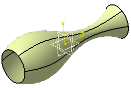
- You can create multi-sections surfaces between closed section curves.
These curves have point continuity at their closing point.
This closing point is either a vertex or an extremum point automatically detected and highlighted by the system.
By default, the closing points of each section are linked to each other.The red arrows in the figures below represent the closing points of the closed section curves. You can change the closing point by selecting any point on the curve. 
The surface is twisted: A new closing point has been imposed to get a non-twisted surface:
Relimitating the Multi-sections Surface
You can choose to limit the multi-sections surface only on the Start section, only on the End section, on both, or on none.
- when none of the options are checked: the swept surface is extrapolated up to the spine limits.
- when both options are checked: the multi-sections surface is limited to corresponding sections
- when one or both options are unchecked: the multi-sections surface is
swept along the spine:
- if the spine is a user spine, the multi-sections surface is limited by the spine extremities or by the first guide extremity met along the spine.
- if the spine is an automatically computed spine, and no guide is
selected: the multi-sections surface is limited
by the start and end sections - if the spine is an automatically computed spine, and one or two guides are selected: the multi-sections surface is limited by the guides extremities.
- if the spine is an automatically computed spine, and more than two guides are selected: the spine stops at a point corresponding to the barycenter of the guide extremities. In any case, the tangent to the spine extremity is the mean tangent to the guide extremities.
Using a Canonical Element
to be used as planes for features needing one in their definition.
Initial multi-sections surface with planar faces Using a planar face as reference for a sketch Resulting sketch
Coupling
These couplings compute the distribution of isoparameters on the surface.
Open the Loft2.CATPart document.
Coupling between two consecutive sections
Coupling between guides
- Ratio: the curves are coupled according to the curvilinear
abscissa ratio.
- Tangency: the curves are coupled according to their
tangency discontinuity points. If they do not have the same number of
points, they cannot be coupled using this option.
- Tangency then curvature: the curves are coupled according to their tangency continuity first then curvature discontinuity points. If they do not have the same number of points, they cannot be coupled using this option.
- Vertices: the curves are coupled according to their vertices. If they do not have the same number of vertices, they cannot be coupled using this option.
Manual Coupling
-
Select the sections for the multi-sections surface, and check their orientations.
-
In the Coupling tab, choose the Tangency option and click Preview.
-
Click in the coupling list, or choose Add in the contextual menu, or using the Add button, and manually select a point on the first section.
The Coupling dialog box is displayed. 
-
Select a corresponding coupling point on each section of the multi-sections surface.
The Coupling dialog box is updated consequently, and the coupling curve is previewed, provided Display coupling curves is selected. When a coupling point has been defined on each section, this dialog box automatically disappears. 
-
Click OK.
The multi-sections surface is created as defined with the coupling specifications. 
The same multi-sections surface without coupling and with Ratio option would have looked like this: 
Note the increased number of generated surfaces.
- You can create coupling point on the fly, using the
Create coupling point contextual menu item (click in the 3D
area
to display the contextual menu) instead of selecting an existing point. - To edit the coupling, simply double-click the coupling name in the list (Coupling tab) to display the Coupling dialog box. Then you select the point to be edited from the list and create/select a replacing coupling point, then click OK.
- Use the contextual menu on the coupling list to edit defined
couplings.
Area Law
- planar sections (with no tangency conditions)
- a spine (optional)
-
a guide curve (either no guide curve, one or two guide curves).
Let's define the law that will be used to create the multi-sections surface.
In our example, we have created three sketches, a curve and a line.
|
|
The Area Law tab is available only with the CFO and GSO licenses. |
Open the Loft4.CATPart document.
-
Click Measure Item
 to measure the distance between Sketch. 1 and Sketch.3.
 -
Using the Sketcher, create a line and a curve corresponding to the previous computed lengths.
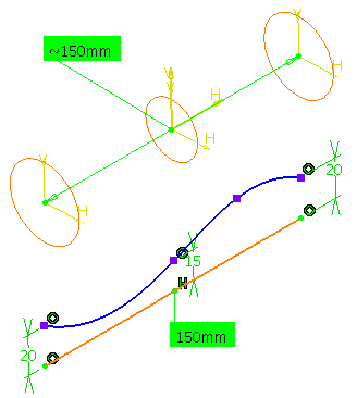
The distance values (20, 15 and 20) are similar to the radius values of the corresponding sections
(that is R=√(A/π) where A is the section area). -
Click Extract
 to create separate elements of the
line and curve.
to create separate elements of the
line and curve.
The two separate elements Extract.1 and Extract. 2 are created. -
Click Law
 to create the law from the previously
extracted elements.
to create the law from the previously
extracted elements.
The Law definition dialog box appears. -
In the Reference box, select a line.
-
In the Definition box, select a curve.
-
Click OK to create the law.
-
Click Multi-sections Surface
.
The Multi-sections Surface Definition dialog box appears. -
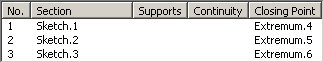
Select the sketches as the planar section curves.
-
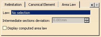
Select the Area law tab.
This tab is only available with the Generative Shape Optimizer product. -
In the Law box, specify the length law to be used to control the section area.
Here, select the law we have just created.
The Intermediate sections deviation option only applies to intermediate sections (unlike the Deviation check box that applies to the sections extremities) and is homogeneous with the selected law. It specifies the deviation of the length law to be applied to the intermediate sections to smooth the resulting shape. -
Click OK to create the multi-sections surface.
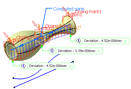
You can select the Display computed area law check box to display in the 3D geometry: - You need to first initiate the computation of law before displaying its computed area in the 3D geometry. Double-click the law in the tree and then click Preview to display the computed area.
- Red indicates the area law.
- Blue indicates the sections areas and a flag on each section that displays the deviation between the area law and the sections areas as well as the equivalent radius of each section.
![]()