-
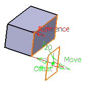
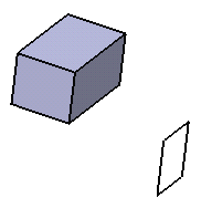
Prior to isolating the plane, note that if you edit the offset value...

...you can obtain this kind of result: 
-
Right-click the plane as the element you want to isolate.

-
Select the xxx object > Isolate command from the contextual menu.
The geometrical link between the plane and the face is no longer maintained. This means that the face is no longer recognized as the reference used to create the plane, and therefore, you can no longer edit the offset value.
The way the plane was created is ignored. You can check this by double-clicking the plane: the Plane Definition dialog box that appears indicates that the plane is of the explicit type.
In the specification tree, the application indicates isolated elements via a red symbol in front of the geometrical element.
![]()
- An isolated feature becomes a datum feature. For more information, refer to Creating Datums.
- When topological naming of a feature depends on its parent's topological naming, the element cannot be isolated.
- When elements are imported using multi-part links (external
references) or using a Copy-Paste As result with link, the Isolate
command
is not available through the contextual menu. Use the Edit > Links and Relations menu bar item instead. For more information, refer to Editing Links and Relations in the Infrastructure User's Guide.
![]()