This task shows how to create a surface by extruding a profile along a given direction.
Open the Extrude1.CATPart document.
-
Click Extrude
 .
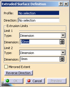
.The Extruded Surface Definition dialog box appears. 
-
Select the Profile to be extruded (Sketch.1).
-
Specify the desired extrusion Direction (xy plane).

-
You can select a line to take its orientation as the extrusion direction or a plane to take its normal as extrusion direction.
-
You can also specify the direction by means of X, Y, Z vector components by using the contextual menu
on the Direction field. -
By default, a normal direction to the plane, on which the profile lies is selected. You need to specify the direction, when a line is selected as a profile to be extruded.
-
-
Define the Extrusion Limits for Limit 1 and Limit 2.
-
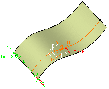
Dimension: enter length values or use the graphic manipulators to define the start and end limits of the extrusion.
Here we defined a length of 30mm for Limit 1 and 80mm for Limit 2.

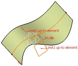
Up-to element: select a geometric element. It can be a point, a plane or a surface (wires are not allowed).
If a point is specified, the up-to element is the plane normal to the extrusion direction passing through the given point.Here we selected Point.1 as Limit 1 and Plane.1 as Limit 2. 
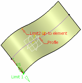
You can also select different extrusion limits, for instance a Dimension for Limit 1 and an Up-to element for Limit 2: 

- The Up-to element can intersect the profile and the surface to be extruded. In the later case, it must completely cut the surface and there should not be any partial intersections of the up-to element with the surface.
- If you select two up-to elements, they must not cut each other within the surface to be extruded.
-
-
Select the Mirrored Extent check box to extrude the profile in the opposite direction using the same dimension value as the one defined for the first dimension.
This option is only available with the Dimension type. -
You can click Reverse Direction or the red arrow in the 3D geometry to display the extrusion on the other side of the selected profile.
-
Click OK to create the surface.
The surface (identified as Extrude.xxx) is added to the specification tree. 
Parameters can be edited in the 3D geometry. For further information, refer to Editing Parameters.
![]()