Open an existing document.
-
Click Extrapolate
 .
.The Extrapolate Definition dialog box appears. -
Pause over a boundary in the 3D geometry area.
The command automatically computes the geometrically feasible extrapolated surface(s). There are two possible scenarios:- When there is only one extrapolated surface,
 appears
over the selected boundary, along with a tooltip. The tooltip
displays the information about the boundary and its support that
will be set as the extrapolated surface.
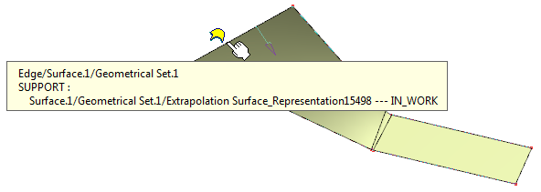
Click the surface boundary. - When there is more than one extrapolated
surface,
 appears. The accompanying tooltip indicates the boundary
and its possible supports, one of which can be used as the
extrapolated surface.
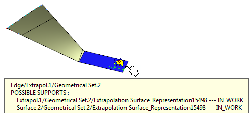
In this case, you can perform either of the following:
- Right-click to display a list of all the possible extrapolated surfaces. Pause over one of the entry to display the corresponding extrapolated surface in the 3D geometry area. Click to confirm your selection.
- Click the surface boundary. The command automatically selects the first entry from the list of possible extrapolated surface solutions and computes the extrapolated surface.
The boundary and its associated extrapolated surface selection appears in the Boundary and Extrapolated box, respectively. - When there is only one extrapolated surface,
-
Optionally, in the Extrapolated box, select the surface to be extrapolated.

This step is necessary only when the command is unable to automatically compute the extrapolated surface or when you want to manually select the extrapolated surface. -
Select the surface to be Extrapolated.
-
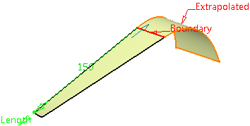
Select the extrapolation Type:
-
Length: enter the value in the Length field or use the manipulators in the 3D geometry.

It is not advised to enter a negative value in the Length field.
-
Up to element : The Up to field is enabled. Select a plane or a surface that intersects the surface that is being added to the original surface by extrapolation. The up to element relimits the extrapolation.
-
-
Specify the Limit of the extrapolation by either:
-
entering the value of the extrapolation length
-
selecting a limit surface or plane
-
using the manipulators in the geometry.
-
-
Specify the Continuity type:
-
Tangent: The resultant surface is tangent continuous to the extrapolated surface at the boundary.
-
Curvature: The resultant surface is curvature continuous to the extrapolated surface at the boundary.
When the continuity type is Curvature, you can select multiple edges of the surface to be extrapolated. You can click  to view and manage the selected edges.
 -
-
Specify Extremities conditions between the extrapolated surface and the support surface.
-
Tangent: The extrapolation sides are tangent to the edges adjacent to the surface boundary.
-
Normal: The extrapolation sides are normal to the original surface boundary.
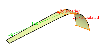
Tangent Extremity (Tangent Continuity) Tangent Extremity (Curvature Continuity) 

Normal Extremity (Tangent Continuity) Normal Extremity (Curvature Continuity) 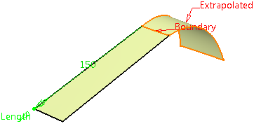
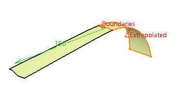
-
-
Specify the Propagation mode:
-
None: No propagation.
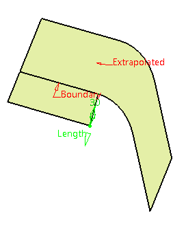
-
Tangency continuity: To propagate the extrapolation to the boundary's adjacent edges.
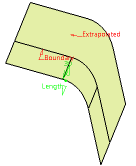
-
Point continuity: To propagate the extrapolation around all the boundary's vertices.
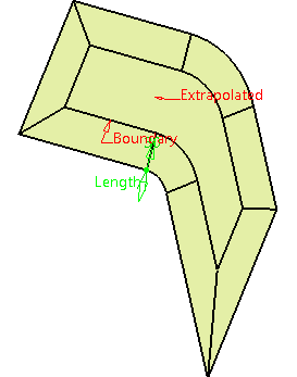
-
-
Optional: Select the Deviation check box and specify a desired value in the box.
In some cases, the extrapolation operation fails, due to creation of a gap between adjacent surfaces. The deviation value avoids creation of such gaps by considering a little difference between the obtained and theoretically calculated extrapolated surface result. This makes the extrapolation operation more robust.
In case of a failure, an error message informs you about the required changes in the deviation value.
- This check box is only available in the Curvature mode.
- By default, when the Deviation check box is selected, the deviation value is the factory resolution (0.001 mm). This value is the minimum length of a valid object.
-
Click OK to create the extrapolated surface.
The surface (identified as Extrapol.xxx) is added to the specification tree.
Additional Parameters
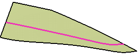
- Checking Constant distance optimization
performs an extrapolation with a constant distance and create a surface
without deformation.

This option is not available when the Federate extrapolated edges option is checked, and also when Limit Type is Up-to element.
- Select Boundary.1 as the Boundary and Surface.1 as the surface to be Extrapolated.
- Set a Length of 10mm.
- Check the Constant distance optimization option.
- Click OK to create the extrapolated surface.
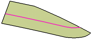
Constant distance optimization option checked
Constant distance optimization option unchecked
- Defining Internal Edges enables to determine a privileged direction for the extrapolation. You can select one or more edges (in the following example we selected the edge of Surface.1) that will be extrapolated in tangency. You can also select a vertex once you have selected an edge in order to give an orientation to the extrapolation.
You can only select edges in contact with the boundary.
This option is not available with the Curvature continuity type and with the Wireframe and Surface product.
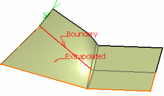
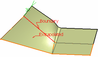
One edge selected
Two edges selected
-
Checking Assemble result enables the extrapolated surface to be assembled to the support surface.
-
Checking Federate extrapolated edges reconnects the features based on elements of the extrapolated surface.
This option is especially useful if you work within an ordered geometrical set environment. In some confusing cases (for instance shallow angles), this option may give a more accurate result as it takes into account the geometry rather than the topology.
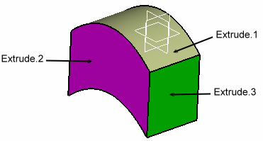
Open the Extrapolate3.CATPart document.
-
Set Extrude.1 as the current object.
-
Select the boundary of Extrude.1 and Extrude.1 as the surface to be extrapolated.
Extrude.3 is automatically rerouted, as well as all edges based on Extrude.1. 
- This option is only available when both Continuity and Extremity types are specified as Tangent, and when Assemble result is selected.
- It is not available when Constant distance optimization is selected.
-
Clearing the Exact boundaries check box switches the boundary computation mode to approximate. It allows more tolerance in the boundary computation, improving the success rate of the extrapolation operation. In the approximate mode, some edges of the boundary may be combined and thus the extrapolation distance may not be precise.

- This check box is available only in the Curvature continuity type.
- By default, this check box is selected.
| In the Knowledge Base Cases where the Extrapolate command cannot automatically valuate the support |
![]()
