This task shows you how to extrapolate a curve.
Open an existing document.
-
Click Extrapolate
 .
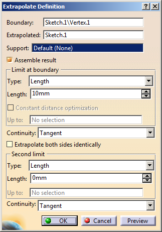
.The Extrapolate Definition dialog box appears. -
Select an endpoint on a curve.
-
Select the curve to be Extrapolated (it can be a wire, an edge, a curve or a line).
-
Select the extrapolation type:
-
Length: Enter the value in the Length field or use the manipulators in the 3D geometry.

It is not advised to enter a negative value in the Length field.

In Curvature mode, the length is the distance of wire obtained through tangent extrapolation relimited by the plane created at the given length from the chosen extremity. This plane is used to split the extrapolated curve. -
Up to element: The Up to field is enabled. Select an element belonging to the same support as the curve to be extrapolated (curve, surface or plane).

The element must intersect the curve to be extrapolated.
-
-
Specify Continuity conditions:
-
Tangent: The extrapolation side is tangent to the curve at the selected endpoint.
Length Extrapolation in Tangent Mode Up to Element Extrapolation in Tangent Mode 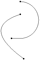
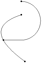
-
Curvature: The extrapolation side complies with the curvature of the selected curve.
Length Extrapolation in Curvature Mode Up to Element Extrapolation in Curvature Mode 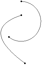
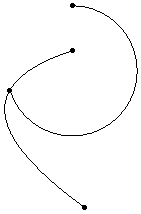
Extrapolation without support Extrapolation with a support 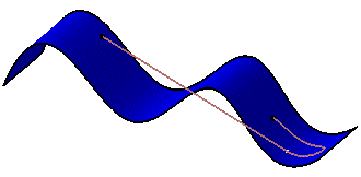
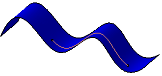
-
-
Specify the extrapolation type and continuity for extrapolating the second side of the curve.

You can select the Extrapolate both sides identically check box to use the same extrapolation type and continuity for the second limit. -
Click OK to create the extrapolated curve.
![]()