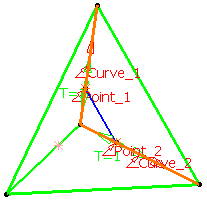
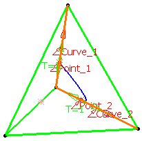
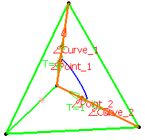
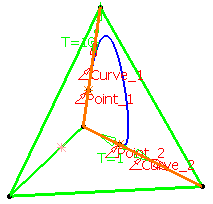
This task shows how to create a connecting curve between two curves.
Open the ConnectCurve1.CATPart document.
-
Click Connect Curve
 .
.The Connect Curve Definition dialog box appears. -
Select the Connect type.
Normal
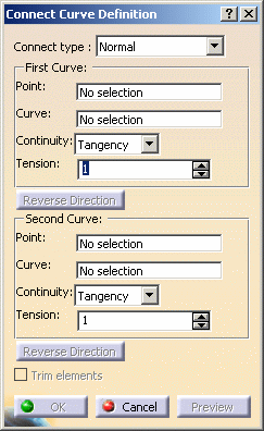
- Select a first Point on a curve then a second
Point on a second curve.
The Curve fields are automatically filled.
Base Curve

This type is only available with the Generative Shape Design 2 product. The Base Curve option is useful when creating several profiles or guides that have the same shape. 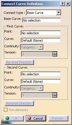
- Select a base curve as the curve reference.
The orientation of the connect curve will be the orientation of the base curve. - Select a first Point on a curve then a second
Point on a second curve.
It can be either on the base curve or on the support curve.

Selecting the support curve is optional (it is set as Default). 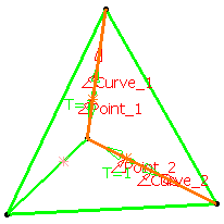
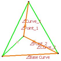
Normal curve Base Curve - Select a first Point on a curve then a second
Point on a second curve.
-
Use the drop-down lists to specify the desired Continuity type: Point, Tangency or Curvature.
-
If needed, enter tension values.
-
Click the arrow to reverse the orientation of the curve at that extremity or click Reverse Direction.

If the Base Curve type is selected, the Reverse Direction buttons are grayed out. -
Check the Trim elements option if you want to trim and assemble the two initial curves to the connect curve.

If the Base Curve type is selected, you must select a support curve to access the Trim elements option. Otherwise, it is grayed out. -
Click OK to create the connect curve.
The curve (identified as Connect.xxx) is added to the specification tree. 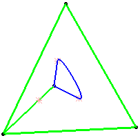
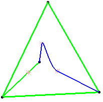
Normal curve with tangent continuity at both points
Both tensions = 1Base Curve
Trim elements option checked
![]()
