|
-
Click Circular Pattern
 . .
-
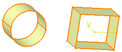
Select the element to replicate as a pattern.
| Here we selected the multi-sections surface. |
| The Circular Pattern Definition dialog box is displayed. |
 |
-
Click the Reference element field and select a
direction to specify the first direction of creation, that is the
rotation axis (Line.2).
| To define a direction, you can select a line, an edge or a planar
face. Should you select a face, the rotation axis would be normal to
that face. |
| You can click Reverse to inverse the rotation
direction. |
-
Define the Axial Reference by choosing the
Parameters type:
-
Click the Crown Definition tab, and choose
which parameters you wish to define the crown.
| This figure may help you define these parameters: |
 |
- Circle(s) & crown thickness: you define the number
of circles and they are spaced out evenly over the specified crown
thickness
- Circle(s) & circle spacing: you define the number
of circles and the distance between each circle, the crown
thickness being computed automatically
- Circle(s) spacing & crown thickness: you define
the distance between each circle and the crown thickness, and the
number of circles is automatically computed.
|
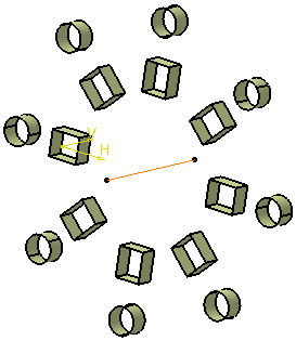
| For instance, using the values described above for the
Angular spacing & total angle option, you could define the
crown as: |
 |
 |
| Note that a few patterns are created beyond the surface.
|
| You can delete the instances of your choice when creating or
editing a pattern. To do so, just select the points materializing
instances in the pattern preview. |
| The instance is deleted, but the point remains, as you may wish
to click it again to add the instance to the pattern definition
again. |
 |
-
Click More>> to display further options:
| These options let you position the instances in
relation to the first selected element. |
 |
| Using these options, you can change the position of
the selected element within the crown. For example, if you set the
Rotation angle parameter to 30°
and you uncheck the Radial alignment of instance(s)
option, this is what you obtain: the initially selected element has
moved 30°
from its initial location, based on the rotation direction, and all
instances are normal to the lines tangent to the circle. |
 |
| The Simplified representation option lets
you lighten the pattern geometry, when more than 15 instances are
generated. What you need to do is just check the option, and click
Preview. The system automatically simplifies the geometry: |
 |
 |
| Not simplified geometry |
Simplified geometry |
| |
| You can also specify the instances you do not want to
see by double-clicking them . These instances are then represented in
dashed lines during the pattern definition and then are no longer
visible after validating the pattern creation. The specifications
remain unchanged, whatever the number of instances you view. This
option is particularly useful for patterns including a large number
of instances. |
| When checking Radial alignment of instances,
all instances have the same orientation as the original feature. When
unchecked, all instances are normal to the lines tangent to the
circle. |
-
Click OK to create the pattern.
| The pattern (identified as CircPattern.xxx) is added
to the specification tree. |
 |
 |
- Patterning User Features (UDFs) is not allowed.
- You can cut or copy circular patterns provided that it belongs
to the same body.
|
|