|
-
Click Surface Simplification
 in the Operations toolbar.
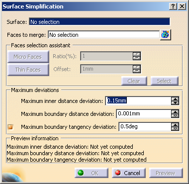
| The Surface Simplification dialog box appears. |
 |
-
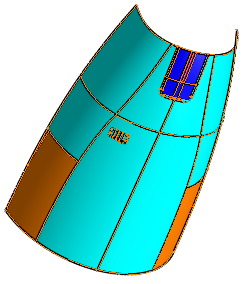
In the Surface box, select the surface to be simplified.
 |
You can select several faces by clicking
 . . |
-
In the Faces to Merge box, select the faces to
be merged from the surface to
be simplified.
-
In the Faces selection assistant area:
You can select the micro faces as the faces to be merged by defining
certain ratio.
| a. |
In the Ratio box, type the value or use the
arrows to enter the ratio of the area of any individual face you
want to
merge with respect to the area of the complete selected surface. |
| |
By default, the ratio is set to 1. |
| b. |
Click Micro faces to select the faces to be
merged. |
| |
Micro faces have the area less than or equal to the ratio
defined. |
| c. |
Click Select to retrieve these micro faces. |
| |
The retrieved micro faces are selected as faces to be merged
and the Faces to merge box is automatically updated. |
| d. |
To cancel the selection, click Clear. |
or
You can select the thin faces as the faces to be merged by defining the
offset value.
| a. |
In the Offset box, define the value by which the
boundary of an individual face can offset inwards. |
| |
By default, the offset value is set to 1mm. |
| |
If a face is created by offsetting the boundaries of an
existing face inwards, with offset value more than or equal
to
the value defined in the offset box. If this new face does not
have any matter, it is defined as a thin face. |
| b. |
Click Thin faces to select all such faces to be
merged. |
| c. |
Click Select to retrieve these thin faces. |
| |
The retrieved thin faces are selected as faces to be merged
and the Faces to merge box is automatically updated. |
| d. |
To cancel the selection, click Clear. |
-
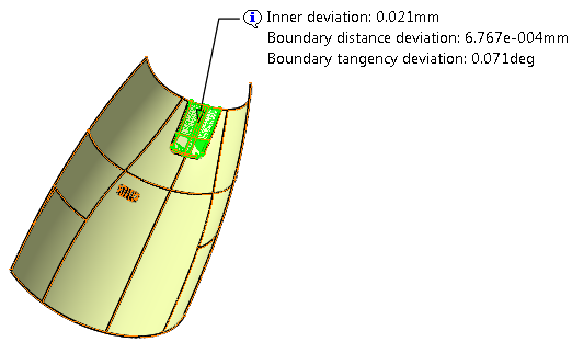
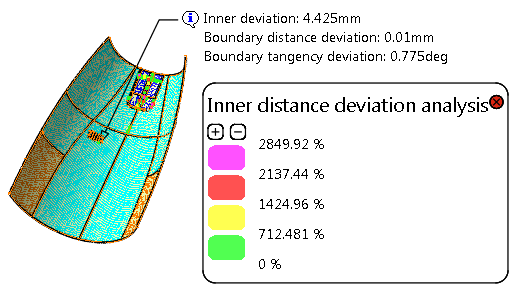
Click Preview.
In the Preview information area, you can visualize the deviation
information. The same information is visible in the 3D geometry area
when you pause over the Maximum Deviations balloon.
-
In the Maximum deviations area, you can type
the value or use the arrows to change values in the following boxes:
- Maximum inner distance deviation: allows you
to define the maximum possible inner distance deviation the
resulting
surface can have as compared to the input surface.
By default, it is set to 0.15mm.
- Maximum boundary distance deviation: allows
you to define the maximum possible boundary deviation the
resulting
surface can have as compared to the input surface.
By default, it is set to 0.001mm.
- Maximum boundary tangency deviation: allows
you to define the maximum boundary tangency deviation the
resulting surface can have as compared to the input surface.
By default, the check box is selected and the value is set
to 0.5deg.
|
|
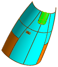
- You can visualize each type of deviation by
selecting it from the Deviation Analysis list. The
points that exceed the maximum deviation are
highlited in the 3D geometry area.
- Each point is color-coded and corresponds to the
percentage of error from the maximum allowed
deviation value:
|
|
-
Optionally, you can visualize each type of deviation by
selecting it from the Deviation Analysis list. The points
that exceed the maximum deviation are highlighted in the 3D geometry
area.
| Each point is color-coded and corresponds to the percentage
of error from the maximum allowed deviation value: |
- 0 % means that the deviation value is the maximum
allowed value.
- 100 % means that the deviation value is 2 times the
maximum allowed value.
- 200 % means that the deviation value is 3 times the
maximum allowed value, and so on.
|
 |
-
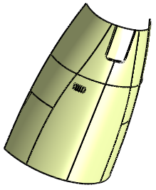
Click OK.
The surface (identified as Surface Simplification.xxx) is
added in the specification tree.
|
|
While editing the simplified surface, the values defined in the
Ratio and Offset boxes for Micro faces
and Thin faces respectively are set to default. |
|