A mold injection process requires that you split a solid model into two sides: the core and the cavity. The core and the cavity are open surfaces, with outer and inner boundaries (holes). You need to fill these holes to construct the splitting surfaces used later in Die Design.
With the cavity surface as input, Fill Surface detects the inner boundaries and creates surfaces to fill those holes. The output is a non connected surface, that you can join respectively with the core and with the cavity.
- Open FillSurface01.CATPart from the samples directory.
-
Click Fill Surface
 in the Surfaces toolbar.
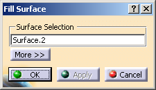
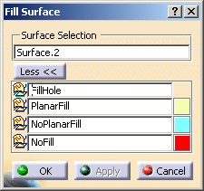
The Fill Surface dialog box is displayed.
-
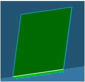
Select the surface with holes to fill (cavity surface) and click Apply.
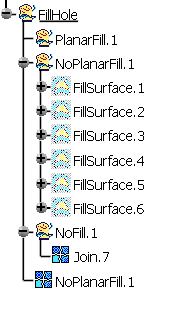
Geometrical sets are created: - FillHole that contains:
- PlanarFill: planar boundaries are
detected and planar fills are created.
If the support of the inner boundary found is made of two planes,

two planar fills are created:
- NoPlanarFill: if the non-planar inner
boundary supports are continuous in tangency,
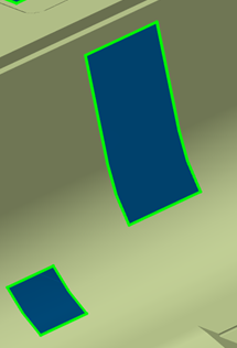
fills are created.
Complex inner boundaries are not filled. - NoFill:contains the inner boundaries that
are not filled, and two points created on each inner
boundaries.
These two points will help you fill those boundaries manually.
- PlanarFill: planar boundaries are
detected and planar fills are created.
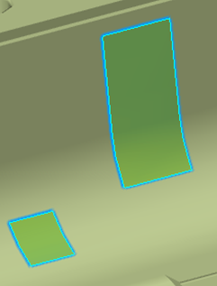
- A PlanarFill join is created with the fills of PlanarFill when they exist.
- A NoPlanarFill join is created with the fills of NoPlanarFill when they exist.
- FillHole that contains:
-
Click More. You can edit the names of the geometrical sets, and modify their color. The corresponding join will have the same name and the same color.
-
Click OK to validate and exit the dialog box.
The fill and join features are created under the specification tree and are editable.
![]()