- Open SewSurface01.CATPart from the samples directory.
-
Insert a Geometrical Set and make it the Define in Work Object.
-
Click Sew Surface
 in the Blocks toolbar.
Do not select faces yet!
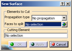
The dialog box is displayed.
-
- No propagation: you select the faces one by one.
- Tangent continuity: you select one face. All the faces in the same body that are tangent to the selected face are automatically selected.
-
Select either one face to split by direct pick, or several with the multi-selection:
- Click
 to display the selected elements.
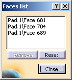
- Pick an element in the 3D viewer or the specification tree to add it to the selection.
- Select an element in the list, then click Remove to remove it from the list.
- Click Reset to reset the whole selection.
- Click Close to revert to the main dialog box.
- Click
-
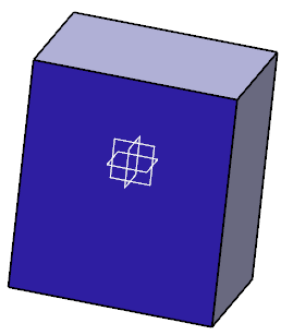
Go to Cutting Element and select the cutting element, e.g. xy plane.
-
Click Apply then OK.
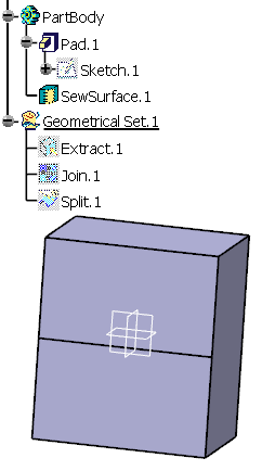
A SewSurface.x feature is created under PartBody.
The construction features of this surface are created under the Geometrical Set.
-
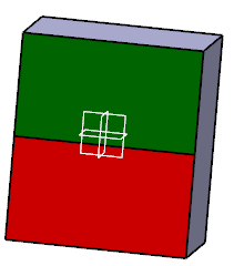
You can now go to the Face Color Editor and color the SewSurface in green and the other in red.
![]()