This command manages the selection of:
- a surface,
- an axis system,
- a profile.
The result Generative Form Block is composed of:
- a body that contains the component itself,
- a body that represents the impacting pocket of the component.
This Generative Form Block can then be turned into an insert in Mold Tooling Design.
A Generative Form Block is made of a Pad (in the Mold Tooling Design sense),
- the Pad is created in the PartBody,
- it can have a chamfer,
- it can be drafted.
and of a Pocket ( (in the Mold Tooling Design sense, optional):
- the pocket is created in DrillHole,
- it can have a fillet,
- it can be drafted.
- Open FormBlock01.CATPart from the samples directory.
- Go to Tools > Options > Infrastructure > Part Infrastructure > Display and select Parameters and Relations under Display in Specification Tree
-
Click Generative Form Block
 in the Blocks toolbar.
The Generative Form Block dialog box is displayed. -
Select the inputs for the block:
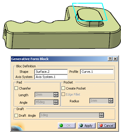
-
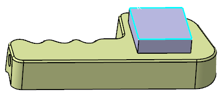
Click Apply. The Pad is created between the surface selected as the Shape and the Profile.
-
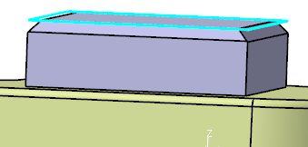
You can create a Chamfer on that Pad:
- Select the Chamfer check box, Length and Angle become editable.
- Key in the Length and the Angle of the chamfer.
- The Chamfer is created automatically on the Pad, and updated as you modify the Length and Angle.
-
- Select the Create Pocket check box.
- Edge Fillet becomes active.
- Select Edge Fillet, Radius becomes editable. Key in the required value.
- The Pocket is created automatically, the Edge Fillet (if any) is updated as you modify the Radius.
-
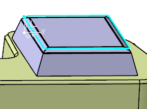
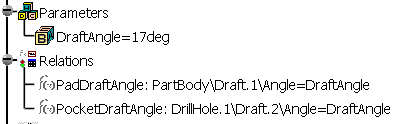
You can apply a Draft Angle to the Pad (or to both the Pack and the Pocket if you have created one).
- Select the Draft Angle check box.
- Its value becomes editable. Key in the required value.
- The Pad and the Pocket are drafted.
-
Click OK to validate and exit the dialog box.
- The Pad and its Chamfer and
Draft (if any)
are created under PartBody.
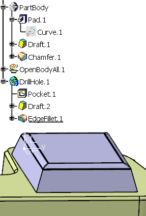
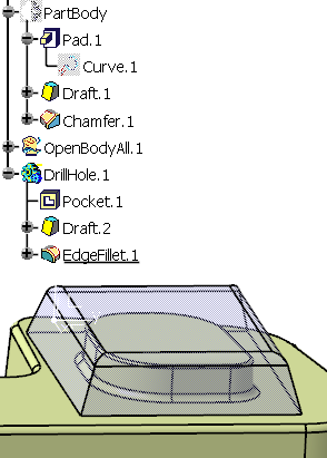
- The Pocket (if any) and its EdgeFillet
and Draft
(if any) are created under a DrillHole body. (in
the picture below, the Pad is hidden.)
- Parameters and Relations are
created.
- The features created are editable.
- The Pad and its Chamfer and
Draft (if any)
are created under PartBody.
![]()