Go to Tools > Options > Infrastructure > Part Infrastructure > Display and select Parameters under Display in Specification Tree
-
Open FilterCover.CATPart in the samples/import directory.
-
Click Bounding Box
 in the Models toolbar.
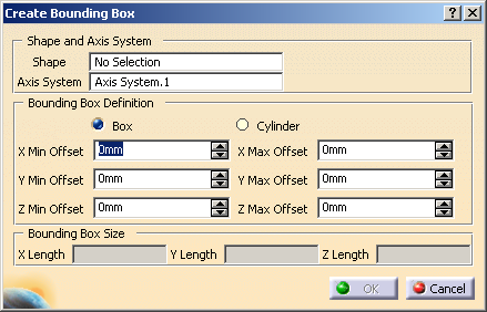
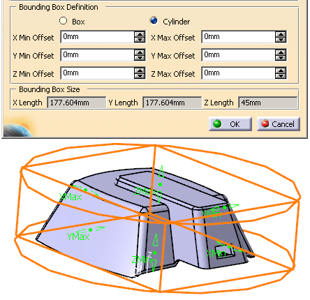
The Create Bounding Box dialog box is displayed.
-
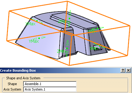
Select a shape and an axis system.
A bounding box is displayed around the shape.
The dialog box is updated.
- The shape must be connex, with no undercut.
- Only direct unit axis systems are supported.
- Negative offset planes are supported.
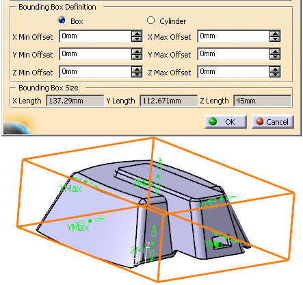
- When the bounding box is a cylinder, X Length and Y Length correspond to the diameter of the cylinder.
-
Click OK to validate and exit the dialog box.
The bounding box is created:
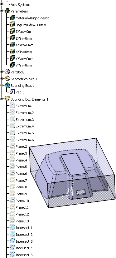
- A pad is created in the Bounding Box.1 body,
- The standard features and parameters are created (respectively in Bounding Box Elements.1 and Parameters bodies) and are editable.
![]()