The batch process is as follows:
- Composites Design:
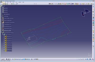
- Creates the ply design in the stacking.
- Simulayt CLBatch
(CATSLTAnaTranBatchCore.exe):
- Reads the ply stacking for the CATIA part file.
- Exports the layup file based on tessellation.
- FEA:
- Maps the layup file on the existing mesh, for example, using Composites Modeler.
Layup files are created using a command file that sets the parameters
needed for the translation.
The command file can be created with any text
editor.
Note that the syntax is very important:
- Be careful with quotes.
- Enclose names containing blank within triple quotes, for example:
-ExportFileName """C:\Documents and Settings\username\My
		Documents\test_actual.Layup"""
-
Create the command file (for example CLBATCH.cmd) to run CATIA using CLBATCH instead of CNEXT.exe.
Example:C:\Program Files\Dassault Systemes\B19\intel_a\code\bin\CATSTART.exe -env Dev19+SLT+CL+AFM
-direnv "C:\Documents and Settings\XXX\Application Data\DassaultSystemes\CATEnv"
-run "CATSLTAnaTranBatchCore.exe -CLCommand ExportPlies -CATPartName S05_Blade_DesignPly_R19.CATPart -Mesh SurfaceTesselation -FiberAngles RegeneratedTheoretical -ExportFileFormat Layup -ExportFileName ./blade_batch.Layup"CATSLTAnaTranBatchCore Command Line Parameters
The parameters and possible values are listed below.
We recommend you create a text file with the parameters and values you need,
and use the option-DefaultOptionsFile options_filewhereoptions_fileis a text file containing the parameters and their values
(one line per parameter, -parameter_name = parameter_value).
Example:-OutputExtrusionOption = NONE
-OutputFirstCoordID = 1
-OutputFirstElementID =
-OutputFirstGPlyID = 1000- Parameters names and values are case sensitive.
- If the file contains a parameter without a set value, the default value is used.
- Parameters starting with Output apply to the options for solvers (the output is not a layup).
- Parameters controlling IDs specify the start point of numbering in
the output file.
If left blank or negative, the translator automatically set an appropriate ID.
Parameter
Type
Valid values
Default
Comments
CLCommandString
ExportPliesExportPliesBatch command name
CATPartNameString
-(user supplied)
Name of CATPart
SelectGroupString
--Selected ply groups, separated by commas.
If no groups are selected, the entire stacking is exported.ExcludeMaterialString
--Materials to be excluded, separated by commas
MaterialRenameFileString
--Name of material rename file
MeshSurfaceTessellation, CoreSamplingSurfaceTessellation-
MeshFileString
--Name of the file that contains the external mesh
(if 'CoreSampling' is selected)MeshFileFormatString
BDF, Layup, CDB, INPBDFSource format of the external mesh
(if 'CoreSampling' is selected)CoreSampleDistanceDouble
>010.0Distance from centroid to look for plies
IncludeCoresInteger
0, 1-Specify whether solids defined as 'cores' are included in Composites Design
TessellationSagValueDouble
>1.0e-60.05Tessellation sag value in mm
TessellationStepValueDouble
>00.0Tessellation step value in mm
ExportOffsetsInteger
0, 10Flag to export surface offset
IgnoreWarningsInteger
0, 10Flag to ignore core sample warnings.
Set to 1 to force writing of output despite errors.FiberAnglesString
RegeneratedTheoretical, RegeneratedActual,
CoreSampleTheoretical,
CoreSampleActualRegeneratedTheoreticalMethod to define the fiber angles
ExportFileFormatString
Layup, Abaqus, Nastran, Ansys, SimXpert, AnsysXMLLayupFormat of export file
ExportFileNameString
-(user-supplied, including extension)
Name of export file
OutputMatOrientationString
MCID, THETATHETAMethod to define the coordinates system in the output file
OutputMatCoordSystemString
--Name of the coordinates system in the output file
OutputAngleToleranceDouble
>0.05.0Angle tolerance in the output file
OutputThickToleranceDouble
>0.0-Thickness tolerance in the output file
OutputIgnoreThicknessInteger
0, 11Specify whether to ignore thickness changes in output file
OutputEquallySpacedDataInteger
0, 10Use equal spacing when grouping data
OutputWriteGlobalPliesInteger
0, 10Use global ply IDs in output file
OutputSectionOffsetString
DEFAULT, TOP, MIDDLE, BOTTOM-Offset of section in output file
OutputWritePlyComponentsInteger
0, 10Write ply components in output file
OutputWriteMatComponentsInteger
0, 10Write material components in output file
OutputFirstPlyIDInteger
>0-Starting ID for plies in output file
OutputFirstGPlyIDInteger
>0-Starting ID for global plies in output file
OutputFirstCoordIDInteger
>0-Starting ID for coodinates in output file
OutputFirstSectionIDInteger
>0-Starting ID for sections in output file
OutputFirstMatIDInteger
>0-Starting ID for materials in output file
OutputFirstNodeIDInteger
>0-Starting ID for nodes in output file
OutputFirstElementIDInteger
>0-Starting ID for elements in output file
OutputReverseElementsInteger
0, 10Reverse elements in output file
OutputPartNameString
--Part name in output file
OutputExtrusionOptionString
NONE, SINGLENONEExtrusion for output file
Example of a Batch Export
CLBATCH Command
SLTClkBatch.exe -CLCommand ExportPlies -CATPartName
		S05_Blade_DesignPly_R19.CATPart -Mesh SurfaceTesselation -FiberAngles
		RegeneratedTheoretical -ExportFileFormat Layup -ExportFileName
		./blade_batch.Layup
Data
- Input file (CATIA V5 CATPart)
-CATPartName
		S05_Blade_DesignPly_R19.CATPart
- Output file: blade_batch.Layup
-ExportFileName
		./blade_batch.Layup
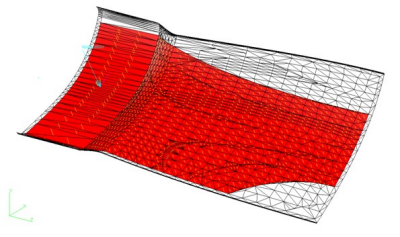
As the exported file is based on a tessellated model, a mapping is required in the analysis tool, or use Composites Link Executable (CLX) (see below) to map this into a Nastran mesh.
Default Options File
-CATPartName = c:\work\myComponent.CATPart

	-CLCommand = ExportPlies

	-CoreSampleDistance = 7.5

	-ExcludeMaterial =

	-ExportFileFormat = Nastran

	-ExportFileName = c:\work\myComponent.bdf

	-ExportOffsets =

	-FiberAngles = RegeneratedTheoretical

	-IgnoreWarnings = 1

	-IncludeCores = 0
      -MaterialRenameFile =
	c:\work\myComponent\renameMaterials.csv

	-Mesh = CoreSampling

	-MeshFile = c:\work\externalMesh.bdf

	-MeshFileFormat = BDF
    -OutputAngleTolerance = 5.0

	 -OutputEquallySpacedData = 0
   -OutputExtrusionOption = NONE

	-OutputFirstCoordID = 1
    -OutputFirstElementID = 2

	-OutputFirstGPlyID = 1000

	-OutputFirstMatID =

	-OutputFirstNodeID =

	-OutputFirstPlyID =
    -OutputFirstSectionID =

	-OutputIgnoreThickness = 1
    -OutputMatCoordSystem =

	-OutputMatOrientation = THETA

	-OutputPartName = "AbaqusPartName"
   -OutputReverseElements =
	0
     -OutputSectionOffset = DEFAULT

	-OutputThickTolerance = 5.0
  -OutputWriteGlobalPlies = 0

	-OutputWriteMatComponents = 0
-OutputWritePlyComponents = 0

	-SelectGroup =
    -TessellationSagValue = 0.1

	-TessellationStepValue = 0.1
Composites Link Executable (CLX)
The purpose of this executable is to map an existing layup file, usually created by Composites Link) onto an existing Nastran Buld Data file (bdf), as a shell mesh.
CLX transfers data as follows:
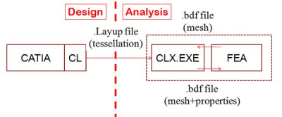
- Simulayt Composites Link
- Exports the layup file based on a tessellation.
- FEA
- Exports a mesh in bdf format.
- Simulayt CLX.EXE
- Reads the layup and mesh.
Maps the layup onto a mesh, creates properties.
Writes the mesh and properties as a bdf file
Template or Macro Updating
CLS can also be used to create a Nastran file with the laminate (PCOMPs and MATs) set to comply with a set of design rules.
This is done by using a template and a macro as input of CLX.
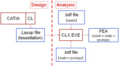
- Template
- Material and properties file
- Macro
- Laminate variation file
- Template/Macro process
-
- Read the mesh file, identify the BasePID, delete existing laminates and materials.
- Import materials and laminate from the material and properties file, set BasePID
- Create variations of laminate using the rules found in the
laminate variations file.
- The closest laminate variation is identified.
- Assign closest laminate to element, based on draping
angle:
- Non-zero angles in base laminate are identifies, for example 45, -45, 90
- On each element, draped angles for plies with
nominal angles equal to these angles are identified,
for examples 32.7, -48.9, 90
(Here, there is no ply with a 90 angle, so the angle is not changed). - Angles not specified in the laminate vairations file are unchanged.
- Delete redundant laminates:
- Unreferenced laminates (pcomps) in output file are deleted for brevity and clarity.
- Use Isolated Property Reduction if applicable.
CLX Command Line Parameters
The used parameters mirror the inputs requried on the nastran Export graphic user interface, plus come additional ones to support the template.
Parameter
Type
Values
Default
Comments
MessageFileString
-Name of message file (optional)
Files specify the data flow.
Mapping tolerances are used for mapping.InputFileString
-Name of input file
InputFileFormatString
NastranNastranFormat of input file
OutputFileString
-Name of output file
OutputFileFormatString
NastranNastranFormat of output file
MapFileString
--Name of map file
MapFileFormatString
LayupLayupFormat of map file
MapAngleToleranceReal
>= 0.045Mapping tolerance
MapDistanceToleranceReal
>= 0.010Mapping tolerance
MaterialOrientationString
(Existing,THETA)THETAAngleToleranceReal
>= 0.015Property merge tolerance
These parameters control the transfer from the ply layup to the laminate definition.
They correspond to the interactive ones.ThicknessToleranceReal
>= 0.015Property merge tolerance
FirstPIDInteger
>01First PID of created property sets
FirstGPlyIdInteger
>=01001If 0, creates PCOMPs
IgnoreThickeningBool
(0,1)1Ignore thickening due to shear
EquallySpacedVariablesBool
(0,1)10,15,…
LaminateReduceItersInteger
>=00Remove isolated laminate refs
LaminateFileString
--Nastran file with MATs & PCOMPs
Only used in the alternative template/macro approach. LaminateVariationsFileString
--Macro for expanding PCOMP
- MessageFile
- Reflects the commands in a message file (useful for debugging
purposes)
$#Layup Lib 20100621 API 20100621 File 20091126
$# Message file opened
$# CLX 1.0
$# -MessageFile : ./Mesh.msg
$# -InputFile : ./Mesh.bdf
$# -InputFileFormat : Nastran
$# -OutputFile : ./Mesh+Mats+Props_makro_reduce99.bdf
$# -OutputFileFormat : Nastran
$# -MapFile : ./Layup.Layup
$# -MapFileFormat : Layup
$# -MapAngleTolerance : 45
$# -MapDistanceTolerance : 10
$# -MaterialOrientation : THETA
$# -AngleTolerance : 0
$# -ThicknessTolerance : 0
$# -FirstPID : 1
$# -FirstGPlyId : 1
$# -IgnoreThickening : 0
$# -EquallySpacedVariables : 0
$# -LaminateReduceIters : 99
$# -LaminateFile : ./Mats+Prop.bdf
$# -LaminateVariationsFile : ./LaminateVariations_15x15.txt MapAngleToleranceandMapDistanceTolerance- In
general, the input file containing the analyis mesh and the map file
containing the layup are on dissimilar meshes.
A mapping is required.MapAngleToleranceandMapDistanceTolerancedefine the maximum allowed angle and distance between the source and destination meshes. MaterialOrientation- Material orientations are defined either from the one existing
in the mesh file, or by computing an angle with respect to the first
edge of each element (
THETA).
With theTHETAoption, the orientation of the lowest ply on each element with a nominal direction of 0 degree is used to define the angle.
Otherwise, the orientation of the lowest ply of an arbitraty direction is used. AngleToleranceandThicknessTolerance- PCOMP/PCOMPG cards are created to reflect the stacking with
respect to the material orientation.
Cards are merged whenever possible usingAngleToleranceandThicknessTolerancevalues defined in degrees and percentage respectively. FirstPID- The first PID value defines the value of the PID of the first
property card.
Usually, PID values correspond to different parts of a model. FirstGPlyId- You can specify a first GPlyID corresponding to the first ply in
the stacking. This value is exported via PCOMPG cards.
With a 0 value, no GPlyIDs are set. PCOMP cards are written insted. IgnoreThickening- Ignores thickening due to shearing, thus reducing the number of properties.
EquallySpacedVariables- When this option is selected, only angles and thicknesses that
are an integer multiple of the input tolerances are used.
For example, if the Angle Tolerance is 15 degrees, only PCOMP layer angles of 0, 15, 30,... degrees are allowed. LaminateReduceIters- Reduces isolated properties:
- If an element with 4(3) sides has 3(2) neighbors sharing the same PID, the element is assigned that PID.
- Can be run several times, until no further changes are made.
