You need access to Composites Design.
-
Select a CATPart containing Composites parameters.
-
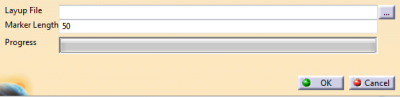
Click ... and select the layup file to import.
When automatic mapping is not possible, you are requested to map the materials manually.
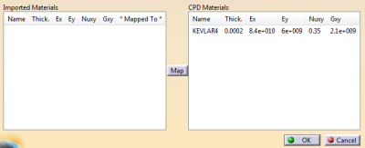
- Pick an analysis material on the left.
- Pick a Composites Design material on the right.
- Click Map.
A spread sheet opens for ply mapping:
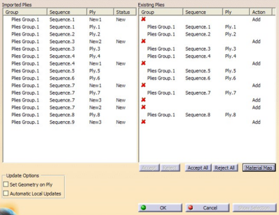
- Imported plies are displayed on the left, existing plies
on the right,
both with their plies group, sequence and ply name. - Composites Link tries to match group, sequence and ply names.
- When a mismatch occurs,
- A status is given for the imported plies.
- An action is proposed on the existing files.
By default, the action is set to Reject (shown by the red cross). - You can accept the action row by row, or accept or reject all actions in one shot.
- You can edit the group, sequence and ply names of
imported plies,
mainly to add group and sequence names to plies created in an analysis environment where names were not required.
The spread sheet is updated automatically.
- Imported plies are displayed on the left, existing plies
on the right,
For a more detailed comparison, select a row and select Show Selection.
A viewer opens with the attributes of the imported and existing plies.
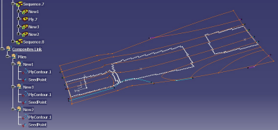
The boundary of the imported ply is displayed in blue.
That of the existing ply is displayed in red.
The surface of the ply group is displayed to help reference, if necessary.
The display is updated as you go to another row.
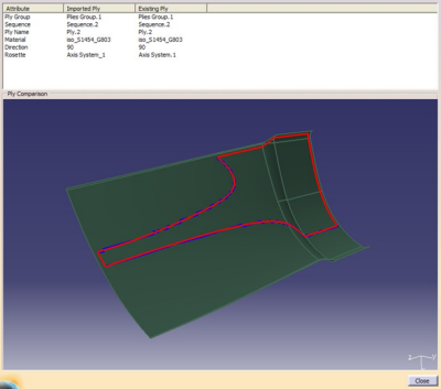
In this example, the imported and existing plies are mostly identical, except that the imported ply is based on an analysis mesh that does not respect the ply boundaries. As a consequence the boundaries of the imported ply is jagged and oscillates about that of the existing design ply.
After you have reviewed all the plies, close the viewer, and accept or reject proposed actions.Select Update Options check boxes:
- Set Geometry on Ply projects the ply contour on the plies group surface.
- Automatic Local Updates completes the projection process automatically.
Both options may be time-consuming.
By default, they are not selected as in most cases you have simplified the ply geometry before associating it to a ply.Click OK.
![]()