This capability is for legacy purposes only.
We recommend you import plies as explained in the next task.
-
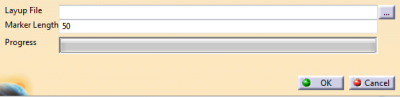
Select a CATPart.
-
Click ... and select the layup file to import.
-
Enter a Marker Length used to create lines that show the reference directons and warp direction at the start point.
Validate.
The selected layup file is parsed (can be time-consuming).
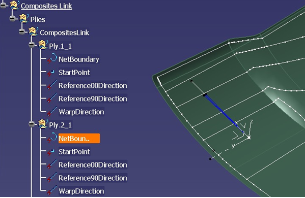
The relevant geometrical entities generated from the ply data are created in a geometrical set named CompositesLink/Plies/layup name.
The uniqueness of the ply names is provided by adding a suffix based on their instance number.
NetBoundary define the outer contour of the ply.
The StartPoint is at the seed point defined in the analysis environment.Reference00and Reference90 directons define the nominal reference directions at the seed point, using lines of 100% and 50% of the input marker length respectively.
The nominal initial wart direction is defined by a line of 75% of the input marker length.
![]()